Infiniti Q45. Manual - part 788


  Index      Infiniti     Infiniti Q45 - service repair manual 2006 year


Search            copyright infringement  


Content   ..  786  787  788  789   ..


Infiniti Q45. Manual - part 788


PRE-CRASH SEAT BELT

SB-31

C

D

E

F

G

I

J

K

L

M

A

B

SB

3. 

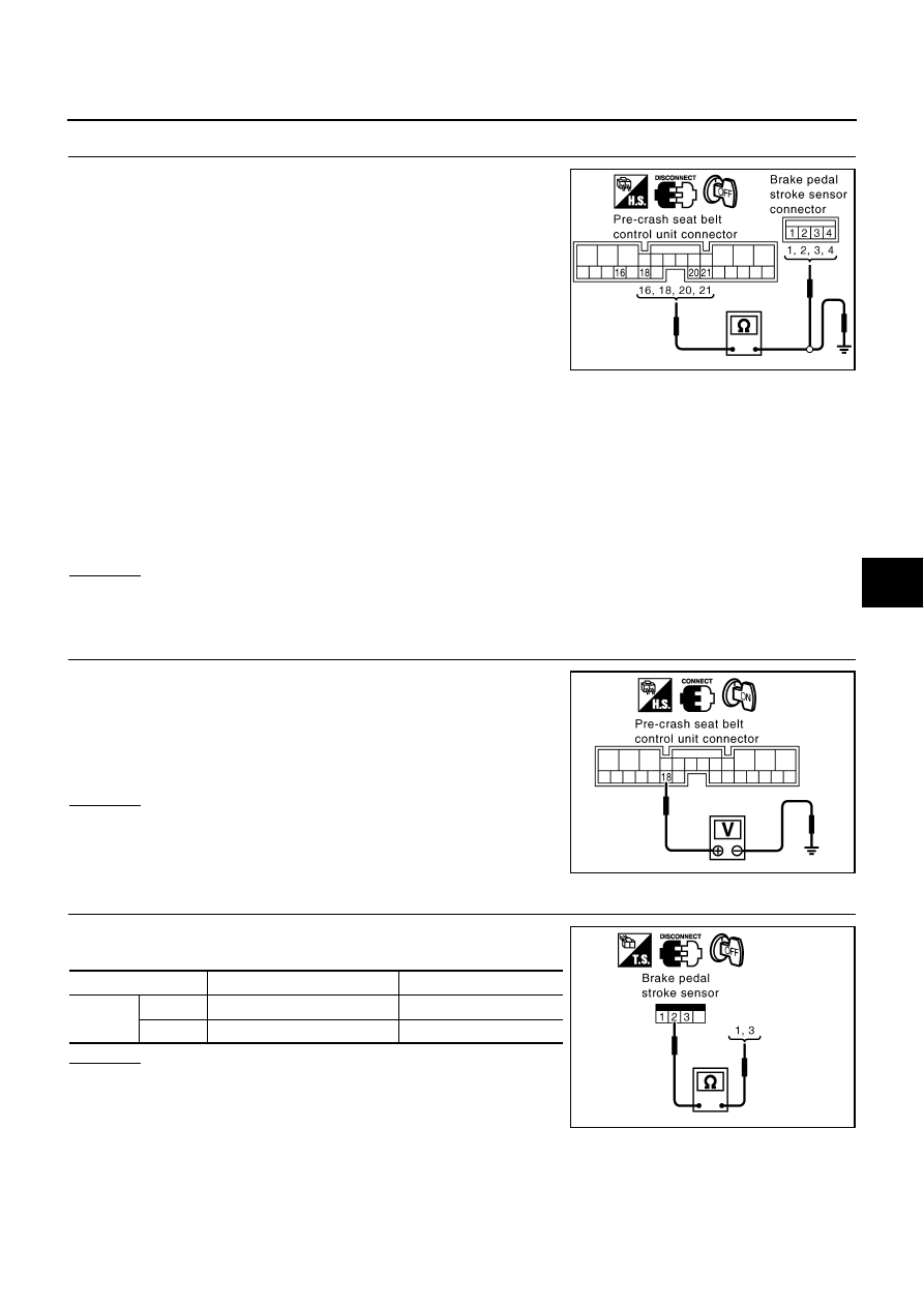
CHECK BRAKE PEDAL STROKE SENSOR HARNESS

1.

Turn the ignition switch OFF.

2.

Disconnect pre-crash seat belt control unit connector and brake
pedal stroke sensor connector.

3.

Check continuity between pre-crash seat belt control unit har-
ness connector B318 terminals 16, 18, 20, and 21 and brake
pedal stroke sensor harness connector M405 terminals 1, 2, 3,
and 4.

4.

Check continuity between pre-crash seat belt control unit harness connector B318 terminals 16, 18, 20,
and 21 and ground.

OK or NG

OK

>> GO TO 4.

NG

>> Repair or replace harness between pre-crash seat belt control unit and brake pedal stroke sensor.

4. 

CHECK BRAKE PEDAL STROKE SENSOR POWER SUPPLY

1.

 Connect pre-crash seat belt control unit connector.

2.

Turn the ignition switch ON.

3.

 Check voltage between pre-crash seat belt control unit harness
connector B318 terminal 18 and ground.

OK or NG

OK

>> GO TO 5.

NG

>> Replace pre-crash seat belt control unit.

5. 

CHECK BRAKE PEDAL STROKE SENSOR

Check continuity between brake pedal stroke sensor terminal 2 and
terminals 1, 3 while performing brake operation.

OK or NG

OK

>> Check harness connection.

If it is OK, replace pre-crash seat belt control unit.

If it is NG, repair or replace malfunction part.

NG

>> Replace brake pedal stroke sensor.

16 (W) - 3(W)

: Continuity should exist.

18 (R) - 2(R)

: Continuity should exist.

20 (G) - 1(G)

: Continuity should exist.

21 (B) - 4(B)

: Continuity should exist.

16 (W) - Ground

: Continuity should not exist.

18 (R) - Ground

: Continuity should not exist.

20 (G) - Ground

: Continuity should not exist.

21 (B) - Ground

: Continuity should not exist.

PHIA0754E

18 (R) - Ground

: Approx. 5V

PHIA0755E

Terminal

Condition

Resistance [K

]

2

1

Brake released 

 depressed

1.0 

 0.2

3

Brake released 

 depressed

0.2 

 1.0

PHIA0756E

SB-32

PRE-CRASH SEAT BELT

Check Pre-Crash Seat Belt Motor LH Circuit [B2452]

NHS00042

1. 

CHECK LH SEAT BELT MOTOR CIRCUIT

 With CONSULT-II

Select “SELF-DIAG RESULTS” of CONSULT-II, and then make sure
that “SB MOTOR LH CIRC” is displayed.

 Without CONSULT-II

When CONSULT-II is not used, omit this inspection, and then GO TO 2.

Displayed B2452?

Yes

>> GO TO 2.

No

>> Pre-crash seat belt motor LH circuit is OK.

2. 

CHECK LH SEAT BELT MOTOR HARNESS

1.

Turn the ignition switch OFF.

2.

Disconnect pre-crash seat belt control unit connector and pre-
crash seat belt motor LH connector.

3.

 Check continuity between pre-crash seat belt control unit har-
ness connector B318 terminals 4, 6 and pre-crash seat belt
motor LH harness connector B117 terminals 1, 2.

4.

Check continuity between pre-crash seat belt control unit har-
ness connector B318terminals 4, 6 and ground.

OK or NG

OK

>> GO TO 3.

NG

>> Repair or replace harness.

3. 

CHECK SEAT BELT MOTOR

 Check continuity between pre-crash seat belt motor LH B117 termi-
nals 1 and 2.

OK or NG

OK

>> Replace pre-crash seat belt control unit.

NG

>> Replace pre-crash seat belt motor LH.

CONSULT-II display

CONSULT-II display code

NO DTC

SB MOTOR LH CIRC

B2452

PHIA0768E

4(GY/W) - 1(G/Y)

: Continuity should exist.

6(L/Y) - 2(G/R)

: Continuity should exist.

4(GY/W) - Ground

: Continuity should not exist.

6(L/Y) - Ground

: Continuity should not exist.

PHIA0757E

1- 2

: Continuity should exist.

PHIA0758E

PRE-CRASH SEAT BELT

SB-33

C

D

E

F

G

I

J

K

L

M

A

B

SB

Check Pre-Crash Seat Belt Motor RH Circuit  [B2451]

NHS00043

1. 

CHECK RH SEAT BELT MOTOR CIRCUIT

 With CONSULT-II

Select SELF-DIAG RESULTS” of CONSULT-II, and then make sure
that “SB MOTOR RH CIRC” is displayed.

 Without CONSULT-II

When CONSULT-II is not used, omit this inspection, and then GO TO 2.

Displayed B2451?

Yes

>> GO TO 2.

No

>> Pre-crash seat belt motor RH circuit is OK.

2. 

CHECK RH SEAT BELT MOTOR HARNESS

1.

Turn the ignition switch OFF.

2.

Disconnect pre-crash seat belt control unit connector and pre-
crash seat belt motor RH connector.

3.

 Check continuity between pre-crash seat belt control unit har-
ness connector B318 terminals 1, 3 and pre-crash seat belt
motor RH harness connector B317 terminals 1, 2.

4.

Check continuity between pre-crash seat belt control unit har-
ness connector B318 terminals 1, 3 and ground.

OK or NG

OK

>> GO TO 3.

NG

>> Repair or replace harness.

3. 

CHECK SEAT BELT MOTOR

 Check continuity between pre-crash seat belt motor RH B317 termi-
nals 1 and 2.

OK or NG

OK

>> Replace pre-crash seat belt control unit.

NG

>> Replace pre-crash seat belt motor RH.

CONSULT-II display

CONSULT-II display code

NO DTC

SB MOTOR RH CIRC

B2451

PHIA0767E

1 (GY/W) - 2(GY/W)

: Continuity should exist.

3 (L/Y) - 1(L/Y)

: Continuity should exist.

1(GY/W) - Ground

: Continuity should not exist.

3 (L/Y) - Ground

: Continuity should not exist.

PHIA0759E

1- 2

: Continuity should exist.

PHIA0758E

SB-34

PRE-CRASH SEAT BELT

Check Brake Pedal Stroke Sensor Shield Wire Circuit 

NHS00044

1. 

CHECK PRE-CRASH SEAT BELT INPUT SIGNAL

 With CONSULT-II

Select “B PEDAL SIG1 and 2” on DATA MONITOR screen, and then
make sure that the voltage does not change if brake pedal is not
operated.
NOTE:
Diagnosis should be performed with engine running, audio and air
conditioner operating.

 Without CONSULT-II

1.

Start engine.

2.

Check voltage between pre-crash seat belt harness connector
B318 terminals 16, 20 and ground without brake pedal opera-
tion.

OK or NG

OK

>> Brake pedal stroke sensor shield wire circuit is OK.

NG

>> Check shield wire for damage. Repair or replace if necessary.

B PEDAL SIG1

Brake released

: There is no change in the voltage 
value, and it is almost constant

B PEDAL SIG2

Brake released

:There is no change in the voltage 
value, and it is almost constant.

Connector

Terminal

(Wire color)

Condition

Voltage [V]

(Approx.)

(+)

(–)

B318

16(W)

Ground

Brake released When 
engine is started and 
audio and air conditioner 
are operating

There is no change in 
the voltage value, and 
it is almost constant.

20(G)

There is no change in 
the voltage value, and 
it is almost constant.

PHIA0766E

PHIA0760E


Content   ..  786  787  788  789   ..