Infiniti Q45. Manual - part 699


  Index      Infiniti     Infiniti Q45 - service repair manual 2006 year


Search            copyright infringement  


Content   ..  697  698  699  700   ..


Infiniti Q45. Manual - part 699


INTERIOR ROOM LAMP

LT-133

C

D

E

F

G

H

I

J

L

M

A

B

LT

CONSULT-II Function (IVMS)

NKS0019X

CONSULT-II can display each diagnostic item using the diagnostic test mode shown following.

CONSULT-II BASIC OPERATION PROCEDURE

CAUTION:

If CONSULT-II is used with no connection of CONSULT-II CONVERTER, malfunctions might be
detected in self-diagnosis depending on control unit which performs CAN communication. 
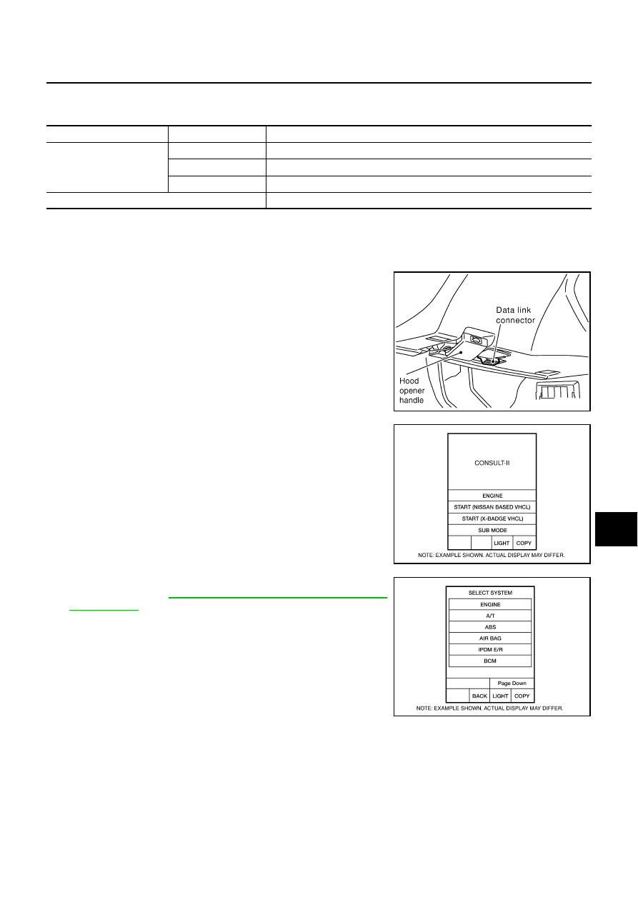
1.

With the ignition switch OFF, connect “CONSULT-II” and “CON-
SULT-II CONVERTER” to the data link connector, and then turn
ignition switch ON.

2.

Touch “START (NISSAN BASED VHCL)”.

3.

Touch “IVMS” on “SELECT SYSTEM” screen. If “IVMS” is not
indicated, refer to 

GI-37, "CONSULT-II Data Link Connector

(DLC) Circuit"

 .

IVMS diagnosis position

Diagnosis mode

Description

INTERIOR ILLUMINATION

WORK SUPPORT

Changes setting of each function.

DATA MONITOR

Displays input data of the BCM and each LCU in real-time.

ACTIVE TEST

Operation of electrical loads can be checked by sending driving signal to them.

BCM PART NUMBER

Displays BCM part number.

PKIB0601E

BCIA0029E

BCIA0030E

LT-134

INTERIOR ROOM LAMP

4.

Select “WITH SUNROOF” on “SELECT SYS COND” screen.

5.

Touch “OK”. If the selection is wrong, touch “CANCEL”.

6.

Select the desired part to be diagnosed on “SELECT TEST
ITEM” screen.

WORK SUPPORT
Operation Procedure

1.

Touch “INTERIOR ILLUMINATION” on “SELECT TEST ITEM” screen.

2.

Touch “WORK SUPPORT” on “SELECT DIAG MODE” screen.

3.

Touch “SET INT-L LOGIC-TIM” or “SET I/L LGC-D-UNLCK” on “SELECT WORK ITEM” screen.

4.

Touch “START”.

5.

Touch “NORMAL”/“MODE 1 - 3” of which setting is to be changed (for the interior lamp logic timer setting
only).

6.

Touch “CHANGE SET”.

7.

The setting will be changed and the current setting status will be displayed.

8.

Touch “END”.

Display Item List

Refer to 

LT-130, "SETTING CHANGE FUNCTION"

 .

DATA MONITOR
Operation Procedure

1.

Touch “INTERIOR ILLUMINATION” on “SELECT TEST ITEM” screen.

2.

Touch “DATA MONITOR” on “SELECT DIAG MODE” screen.

3.

Touch “ALL SIGNALS” or “SELECTION FROM MENU” on “SELECT MONITOR ITEM” screen.

4.

Touch “START”.

5.

When “SELECTION FROM MENU” is selected, touch individual items to be monitored. When “ALL SIG-
NALS” is selected, all the items will be monitored.

6.

Touch “RECORD” while monitoring, then the status of the monitored item can be recorded. To stop
recording, touch “STOP”.

Display Item List

PIIA0184E

ALL SIGNALS

Monitors all items.

SELECTION FROM MENU

Selects items and monitors them.

Monitored item

 [“OPERATION OR UNIT”]

Contents

IGN ON SW

[ON/OFF]

Displays status of the ignition switch as judged from the ignition switch signal. (Key is in ON posi-
tion: ON/Key is in ACC or OFF position: OFF)

DOOR SW-DR

[ON/OFF]

Displays status of the driver door as judged from the driver door switch signal. (Door is open: ON/
Door is closed: OFF)

DOOR SW-AS

[ON/OFF]

Displays “Door open (ON)/door closed (OFF)” status judged from the door switch AS signal.

DOOR SW-RR

[ON/OFF]

Displays “Door open (ON)/door closed (OFF)” status judged from the door switch RR signal.

DOOR SW-RL

[ON/OFF]

Displays “Door open (ON)/door closed (OFF)” status judged from the door switch RL signal.

HD/LMP 1ST SW

[ON/OFF]

Displays status of the lighting switch as judged from the lighting switch signal. (OFF or AUTO 
position: OFF/Other than OFF and AUTO position: ON)

IGN KEY SW

[ON/OFF]

Displays “Key inserted (ON)/key withdrawn (OFF)” status judged from the key remainder detec-
tion switch signal.

INTERIOR ROOM LAMP

LT-135

C

D

E

F

G

H

I

J

L

M

A

B

LT

ACTIVE TEST
Operation Procedure

1.

Touch “INTERIOR ILLUMINATION” on “SELECT TEST ITEM” screen.

2.

Touch “ACTIVE TEST” on “SELECT DIAG MODE” screen.

3.

Touch item to be tested and check operation of the selected item.

4.

During the operation check, touching “OFF” deactivates the operation.

Display Item List

CAUTION:

Active test should be performed with the lamp switch in AUTO position.

On Board Diagnosis

NKS0019Y

BCM can check communication diagnosis, switch monitor, and central locking system self diagnosis using
on board diagnosis.

Map lamps and step lamps (all seats) act as the indicators for on board diagnosis.

DIAGNOSIS ITEM

IGN ACC SW

[ON/OFF]

Displays “Ignition ON or ACC (ON)/ignition OFF (OFF)” status judged from the ignition switch sig-
nal.

LOCK SIG-DR

[LOCK/UNLK]

Displays “Door locked (LOCK)/door unlocked (UNLK)” status judged from the locking detection 
switch DR signal.

Monitored item

 [“OPERATION OR UNIT”]

Contents

Test items

Display on 

CONSULT-II screen

Description

Map lamp output

FR PERSONAL LAMP

Map lamp can be operated by any ON-OFF operation of lights.

Personal lamp output

RR PERSONAL LAMP

Personal lamp can be operated by any ON-OFF operation of lights.

Ignition key hole illumination 
output

KEY RING ILLUM

Ignition key hole illumination can be operated by any ON-OFF operation of 
lights.

Diagnosis item

Description

Switch monitor

Checks for malfunction in switch systems that input to BCM and each LCU.

LT-136

INTERIOR ROOM LAMP

SWITCH MONITOR

Perform diagnosis on the switch system connected to each control unit.

How to Perform Switch Monitor

Description

Detects the status change (switch ON/OFF operation) of switch to be checked, and turns ON/OFF indica-
tor lamps (the map lamp and step lamp). Also sounds the buzzer for 0.5 seconds.

If a malfunction is detected, no indicator lamp and buzzer react.

Switch Monitor Item

The status of the switch (except the ignition switch, interior lamp illumination switch, and map lamp switch)
as input to each control unit can be monitored.

Switch Monitor Cancellation

If the following conditions are satisfied, the communication diagnosis is cancelled.

Turn ignition switch OFF.

Drive the vehicle more than 7 km/h (4 MPH).

PKIA7882E

PIIA0177E

Control unit

Item

BCM

Lighting switch (AUTO, 1ST position)

Each door switch

Driver door LCU

Door locking detection switch


Content   ..  697  698  699  700   ..