Index Infiniti Infiniti Q45 - service repair manual 2006 year
Search copyright infringement
Content .. 359 360 361 362 ..
Infiniti Q45. Manual - part 361
TROUBLE DIAGNOSIS
EC-83
C
D
E
F
G
H
I
J
K
L
M
A
EC
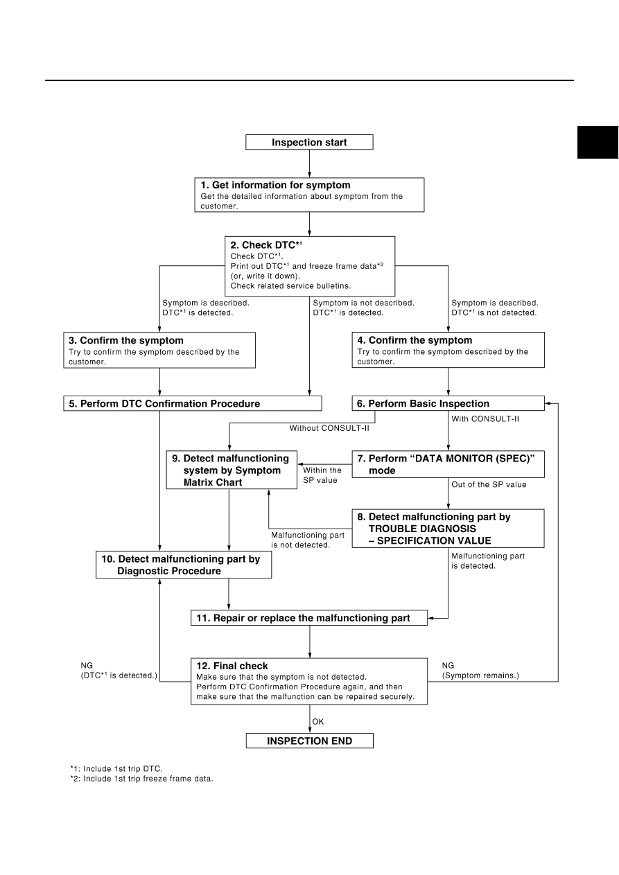
WORK FLOWOverall Sequence
PBIB2267E