Infiniti Q45 (FY33). Manual - part 282
TEL066M
GI
MA
EM
LC
EC
FE
AT
PD
FA
RA
BR
ST
RS
BT
HA
IDX
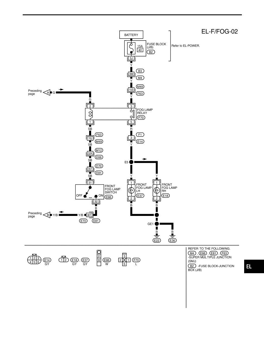
FRONT FOG LAMP
Wiring Diagram — F/FOG — (Cont’d)
EL-119
|
|
|
TEL066M GI MA EM LC EC FE AT PD FA RA BR ST RS BT HA IDX FRONT FOG LAMP Wiring Diagram — F/FOG — (Cont’d) EL-119 |