Infiniti Q45 (FY33). Manual - part 233
SEF600U
SEF594U
SEF427U
SEF419U
q
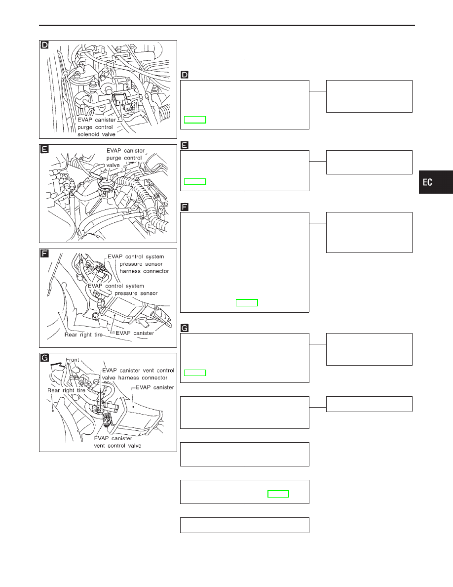
A
CHECK COMPONENT
(EVAP canister purge control solenoid
valve).
Refer to “COMPONENT INSPECTION”,
EC-463.
OK
E
NG
Replace EVAP canister
purge control solenoid
valve.
CHECK COMPONENT
(EVAP canister purge control valve).
Refer to “COMPONENT INSPECTION”,
EC-463.
OK
E
NG
Replace EVAP canister
purge control valve.
CHECK COMPONENT AND CIRCUIT
(EVAP control system pressure sensor).
1. Check disconnection of hose connected
to the sensor.
2. Check sensor harness connector for
water.
Water should not exist.
If OK, go to step 3.
3. Check EVAP control system pressure
sensor. Refer to “COMPONENT
INSPECTION”, EC-320.
OK
E
NG
Replace EVAP control sys-
tem pressure sensor and
repair or replace harness
and connector.
CHECK COMPONENT
(EVAP canister vent control valve and
O-ring).
Refer to “COMPONENT INSPECTION”,
EC-455.
OK
E
NG
Replace EVAP canister
vent control valve and
O-ring.
CHECK EVAP PURGE LINE.
Inspect EVAP purge line (pipe and rubber
tube). Check for evidence of leaks.
OK
E
NG
Replace it.
Clean EVAP purge line (pipe and rubber
tube) using air blower.
Perform “TROUBLE DIAGNOSIS FOR
INTERMITTENT INCIDENT”, EC-117.
INSPECTION END
GI
MA
EM
LC
FE
AT
PD
FA
RA
BR
ST
RS
BT
HA
EL
IDX
TROUBLE DIAGNOSIS FOR DTC P1447
Evaporative Emission (EVAP) Control System
Purge Flow Monitoring (Cont’d)
H
H
H
H
H
H
H
H
EC-461