Infiniti M45 (Y34). Manual - part 645
FRONT FOG LAMP
LT-87
C
D
E
F
G
H
I
J
L
M
A
B
LT
2.
CHECK FRONT FOG LAMP CIRCUIT
1.
Turn ignition switch OFF.
2.
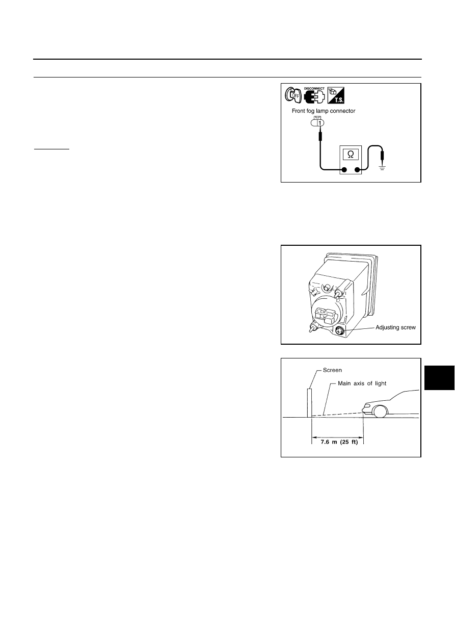
Disconnect front fog lamp connector.
3.
Check continuity between front fog lamp harness connector ter-
minal 1 (B) of lamp which does not illuminate and ground.
OK or NG
OK
>> Check harness for open or short between front fog lamp
relay and front fog lamp.
NG
>> Repair harness.
Aiming Adjustment
AKS003RV
The fog lamp is a semi-sealed beam type which uses a replaceable halogen bulb. Before performing aiming
adjustment, make sure of the following.
●
Keep all tires inflated to correct pressure.
●
Place vehicle on level ground.
●
See that vehicle is unloaded (except for full levels of coolant,
engine oil and fuel, and spare tire, jack, and tools). Have the
driver or equivalent weight placed in driver seat.
Adjust aiming in the vertical direction by turning the adjusting screw.
1.
Set the distance between the screen and the center of fog lamp
lens as shown.
2.
Turn front fog lamps ON.
1 (B) - Ground
: Continuity should exist.
PKIA5920E
PKIA2244E
MEL327G