Infiniti M45 (Y34). Manual - part 458
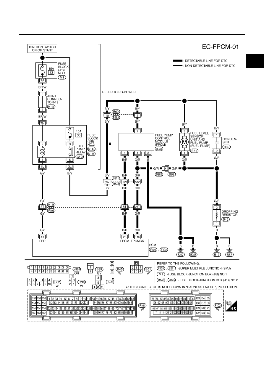
DTC P1220 FUEL PUMP CONTROL MODULE (FPCM)
EC-521
C
D
E
F
G
H
I
J
K
L
M
A
EC
Wiring Diagram
ABS002PW
TBWA0306E
|
|
|
DTC P1220 FUEL PUMP CONTROL MODULE (FPCM) EC-521 C D E F G H I J K L M A EC Wiring Diagram ABS002PW TBWA0306E |