Infiniti M45 (Y34). Manual - part 263


  Index      Infiniti     Infiniti M45 (Y34) - service repair manual 2004 year


Search            copyright infringement  


Content   ..  261  262  263  264   ..


Infiniti M45 (Y34). Manual - part 263


REAR DISC BRAKE

BR-31

C

D

E

G

H

I

J

K

L

M

A

B

BR

CAUTION:

When replacing the pads with new ones, press in the piston until the pads can be installed. In this
case, carefully monitor the brake fluid level in the reservoir tank because the brake fluid will return
to the reservoir tank of the master cylinder.

4.

Insert the lower sliding pin bolt to tighten to the specified torque.

5.

Check the brake for drag.

6.

Attach the tires to the vehicle.

Removal and Installation of Caliper Assembly

AFS000KN

REMOVAL

1.

Remove tire from vehicle.

2.

Connect a vinyl tube to the bleed valve.

3.

Drain brake fluid gradually from the bleed valve while depress-
ing the brake pedal. Refer to 

BR-9, "Drain and Refill"

 .

4.

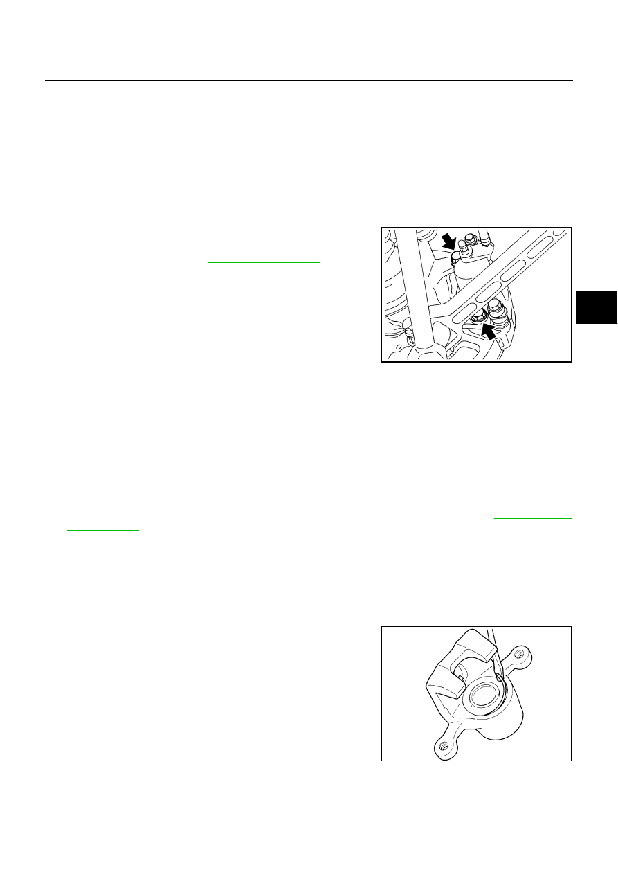
Remove the union bolts, and then remove the brake hose from
the caliper assembly.

5.

Remove the mounting bolts from the torque member, and
remove the caliper assembly from the vehicle.

6.

Remove the disc rotor.

INSTALLATION

1.

Install the disc rotor.

2.

Install the caliper assembly to the vehicle, and tighten the mounting bolts to the specified torque.

CAUTION:

Before installing the caliper assembly to the vehicle, wipe oil and grease on the washer seats on
the axle assembly and mounting surface of the caliper assembly.

3.

Install the brake hose to the caliper assembly and tighten the union bolts to the specified torque.

CAUTION:

Do not reuse the copper washer for union bolts.

Assemble the brake hose securely to the protrusion on caliper assembly.

4.

After installing the caliper assembly, refill with new brake fluid and bleed air. Refer to 

BR-9, "Bleeding

Brake System"

 .

5.

Attach the tires to the vehicle.

Disassembly and Assembly of Caliper Assembly

AFS000KO

DISASSEMBLY

1.

Remove the sliding pin bolts. Then remove the pads, shims, and shim covers from the caliper assembly,
and remove the pad retainers from the cylinder body.

2.

Remove the sliding pin and sliding pin boot from the torque member.

3.

Using a flat-bladed screwdriver as shown in the figure, remove
the retaining ring from the cylinder body.

4.

Place a wooden block as shown in the figure, and blow air from the union bolt mounting hole to remove
the pistons and piston boots.

SFIA0143E

SBR028A

BR-32

REAR DISC BRAKE

CAUTION:

Do not get fingers caught in the piston.

5.

Using a flat-bladed screwdriver, remove the piston seals from
the cylinder body.

CAUTION:

Be careful not to damage the inner wall of the cylinder.

BRD0041D

SFIA2169E

REAR DISC BRAKE

BR-33

C

D

E

G

H

I

J

K

L

M

A

B

BR

INSPECTION AFTER DISASSEMBLY
Cylinder Body

CAUTION:

Use new brake fluid to clean. Never use mineral oils such as gasoline or kerosene.

Check the inner wall of the cylinder for corrosion, wear, and damage. If a malfunction is detected, replace
the cylinder body.

Minor flaws caused by corrosion or foreign material can be removed by polishing the surface with a fine
sandpaper. Replace the cylinder body, if necessary.

Torque Member

Check for wear, cracks, and damage. If a malfunction is detected, replace the applicable part.

Piston

CAUTION:

The piston sliding surface is plated. Do not polish with sandpaper.
Check the piston surface for corrosion, wear, and damage. If a malfunction is detected, replace the applicable
part.

Sliding Pin, Pin Bolt, and Pin Boot

Check the sliding pin and sliding pin boot for wear, damage, and cracks. If a malfunction is detected, replace
the applicable part.

ASSEMBLY

CAUTION:

Do not use Nissan Rubber Grease (KRE00 00010, KRE00 00010 01) when assembling.
1.

Apply brake grease to the piston seals, and install them to the
cylinder body.

CAUTION:

Do not reuse the piston seals.

2.

Apply brake fluid to piston boots. Cover the piston end with the
piston boot, and install the cylinder-side lip on the piston boots
properly into the groove on the cylinder body.

CAUTION:

Do not reuse the piston boot.

3.

Press the piston into the cylinder body by hand to assemble the
piston-side lip on the piston boot properly into the groove on the
piston.

CAUTION:

Press the piston evenly and change the pressing point to
prevent the inner wall of the cylinder from being rubbed.

SFIA2170E

SFIA2171E

BR-34

REAR DISC BRAKE

4.

Fix the piston boot with the retaining ring.

CAUTION:

Make sure that the boot is securely engaged in the
groove on the cylinder body.

Do not reuse the retaining ring.

5.

Install the sliding pins and sliding pin boots to the torque mem-
ber.

6.

Install the pad retainers to the torque member.

7.

After assembling the shims and shim covers to the pads,
assemble it to the torque member.

8.

Install the cylinder body, and tighten the sliding pin bolts to the
specified torque.

DISC ROTOR INSPECTION
Visual Inspection

Check the surface of the disc rotor for uneven wear, cracks, and serious damage. If a malfunction is detected,
replace the applicable part.

Runout Inspection

1.

Using wheel nuts, fix the disc rotor to the wheels hub. (2 or more positions)

2.

Using a dial indicator, check the runout.

CAUTION:

Before measuring, make sure that the axle end play is 0 mm
(0 in).

3.

If the runout is outside the limit, find the minimum runout point by
shifting the mounting positions of the disc rotor and wheel hub by one hole.

Thickness Inspection

Using a micrometer, check the thickness of the disc rotor. If the thick-
ness is outside the standard, replace the disc rotor.

Brake Burnishing Procedure

AFS0029W

Burnish the brake contact surfaces according to the following procedure after refinishing or replacing drums or
rotors, after replacing pads or linings, or if a soft pedal occurs at very low mileage.

CAUTION:

Only perform this procedure under safe road and traffic conditions. Use extreme caution.

1.

Drive the vehicle on a straight smooth road at 50 km/h (31 MPH).

2.

Use medium brake pedal/foot effort to bring the vehicle to a complete stop from 50 km/h (31 MPH). Adjust
brake pedal/foot pressure such that vehicle stopping time equals 3 to 5 seconds.

3.

To cool the brake system, drive the vehicle at 50 km/h (31 MPH) for 1 minute without stopping.

4.

Repeat steps 1 to 3, 10 times or more to complete the burnishing procedure.

SFIA2172E

Measurement point:

 At a point 10 mm (0.39 in) from the outer 
edge of the disc

Maximum runout:

 0.10 mm (0.0039 in) or less

BRA0013D

Standard thickness

: 16.0 mm (0.63 in)

Wear limit

: 14.0 mm (0.55 in)

Maximum uneven wear (measured at 8 positions):

 0.015 mm (0.0006 in) or less

SBR020B


Content   ..  261  262  263  264   ..