Infiniti M35/M45 Y50. Manual - part 996


  Index      Infiniti     Infiniti M35/M45 Y50 - service repair manual 2007 year


Search            copyright infringement  


Content   ..  994  995  996  997   ..


Infiniti M35/M45 Y50. Manual - part 996


SERVICE DATA AND SPECIFICATIONS (SDS)

PR-13

C

E

F

G

H

I

J

K

L

M

A

B

PR

SERVICE DATA AND SPECIFICATIONS (SDS)

PFP:00030

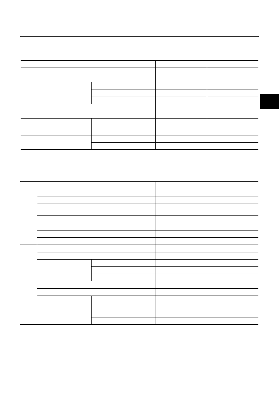
General Specifications

NDS000EH

2WD MODELS

*1: Spider to spider
*2: Spider to rebro joint center
*3: Rubber coupling center to rebro joint center
*4: Rebro joint center to rebro joint center

AWD MODELS

Applied model

 VQ35DE

VK45DE

Propeller shaft model

3S80A-1VL107

3F-R-2VL107

Number of joints

3

Type of journal bearings
(Non-disassembly type)

1st joint

Shell type

Rubber coupling type

2nd joint

Shell type

Rebro joint type

3rd joint

Rebro joint type

Rebro joint type

Coupling method with transmission

Sleeve type

Flange type

Coupling method with rear final drive

Flange type

Shaft length

1st

724 mm (28.50 in)

*1

739 mm (29.09 in)

*3

2nd

803 mm (31.61 in)

*2

802 mm (31.57 in)

*4

Shaft outer diameter

1st

82.6 mm (3.25 in)

2nd

82.6 mm (3.25 in)

Applied model

VQ35DE

Front

Propeller shaft model

2S56A

Number of joints

2

Type of journal bearings
(Non-disassembly type)

Shell type

Coupling method with transfer

Sleeve type

Coupling method with front final drive

Flange type

Shaft length (Spider to spider)

763 mm (30.04 in)

Shaft outer diameter

42.7 mm (1.68 in)

Rear

Propeller shaft model

3F80A-1VL107

Number of joints

3

Type of journal bearings
(Non-disassembly type)

1st joint

Shell type

2nd joint

Shell type

3rd joint

Rebro joint type

Coupling method with transfer

Flange type

Coupling method with rear final drive

Flange type

Shaft length

1st (Spider to spider)

399 mm (15.71 in)

2nd (Spider to rebro joint center)

803 mm (31.61 in)

Shaft outer diameter

1st

82.6 mm (3.25 in)

2nd

82.6 mm (3.25 in)

PR-14

SERVICE DATA AND SPECIFICATIONS (SDS)

Journal Axial Play

NDS000EI

Propeller Shaft Runout

NDS000EJ

Model

Front propeller shaft

Rear propeller shaft

2S56A

3S80A-1VL107

3F80A-1VL107

3F-R-2VL107

Journal axial play

0 mm (0 in)

Model

Front propeller shaft

Rear propeller shaft

2S56A

3S80A-1VL107

3F80A-1VL107

3F-R-2VL107

Propeller shaft runout limit

0.8 mm (0.031 in)

PS-1

POWER STEERING SYSTEM

G  STEERING

CONTENTS

C

D

E

F

H

I

J

K

L

M

SECTION 

PS

A

B

PS

POWER STEERING SYSTEM

PRECAUTIONS .......................................................... 3

Precautions for Supplemental Restraint System 
(SRS) “AIR BAG” and “SEAT BELT PRE-TEN-
SIONER” .................................................................. 3
Precautions Necessary for Steering Wheel Rotation 
After Battery Disconnect  .......................................... 3

OPERATION PROCEDURE  ................................. 3

Precautions for Steering System  .............................. 4

PREPARATION ........................................................... 5

Special Service Tools  ............................................... 5
Commercial Service Tools ........................................ 6

NOISE, VIBRATION AND HARSHNESS (NVH) 
TROUBLESHOOTING ................................................ 7

NVH Trouble Shooting Chart .................................... 7

POWER STEERING FLUID ........................................ 8

Checking Fluid Level  ................................................ 8
Checking Fluid Leakage ........................................... 8
Air Bleeding Hydraulic System  ................................. 8

STEERING WHEEL  .................................................. 10

On-Vehicle Inspection and Service  ........................ 10

CHECKING CONDITION OF INSTALLATION  .... 10
CHECKING STEERING WHEEL PLAY  .............. 10
CHECKING NEUTRAL POSITION STEERING 
WHEEL ............................................................... 10
CHECKING STEERING WHEEL TURNING 
FORCE ................................................................ 10
CHECKING FRONT WHEEL TURNING ANGLE 

....11

Removal and Installation  ........................................ 12

REMOVAL ........................................................... 12
INSTALLATION ................................................... 12

STEERING COLUMN  ............................................... 13

Removal and Installation  ........................................ 13

COMPONENTS .................................................. 13
REMOVAL OF UPPER JOINT, COLLAR, HOLE 
COVER SEAL, HOLE COVER, LOWER SHAFT 
AND LOWER JOINT  ........................................... 14
INSPECTION AFTER REMOVAL  ....................... 14

INSTALLATION OF UPPER JOINT, COLLAR, 
HOLE COVER SEAL, HOLE COVER, LOWER 
SHAFT AND LOWER JOINT  .............................. 14
REMOVAL OF STEERING COLUMN ASSEM-
BLY ...................................................................... 15
INSPECTION AFTER REMOVAL  ....................... 16
INSTALLATION OF STEERING COLUMN 
ASSEMBLY ......................................................... 16
INSPECTION AFTER INSTALLATION ................ 16

Disassembly and Assembly .................................... 17

COMPONENTS ................................................... 17
DISASSEMBLY ................................................... 17
INSPECTION AFTER DISASSEMBLY ................ 17
ASSEMBLY ......................................................... 17
INSPECTION AFTER ASSEMBLY ...................... 18

POWER STEERING GEAR AND LINKAGE  ............ 19

Removal and Installation  ........................................ 19

COMPONENTS ................................................... 19
REMOVAL ........................................................... 19
INSTALLATION ................................................... 20
INSPECTION AFTER INSTALLATION ................ 20

Disassembly and Assembly .................................... 21

COMPONENTS ................................................... 21
DISASSEMBLY ................................................... 22
INSPECTION AFTER DISASSEMBLY ................ 23
ASSEMBLY ......................................................... 25

POWER STEERING OIL PUMP  ............................... 30

On-Vehicle Inspection and Service ......................... 30

CHECKING RELIEF OIL PRESSURE  ................ 30

Removal and Installation  ........................................ 30

REMOVAL ........................................................... 30
INSTALLATION ................................................... 30

Disassembly and Assembly (Models with VK45DE) ... 31

COMPONENTS ................................................... 31
INSPECTION BEFORE DISASSEMBLY ............. 31
DISASSEMBLY ................................................... 32
INSPECTION AFTER DISASSEMBLY ................ 32

PS-2

ASSEMBLY ......................................................... 33

Disassembly and Assembly (Models with VQ35DE) ... 35

COMPONENTS ................................................... 35
INSPECTION BEFORE DISASSEMBLY ............. 35
DISASSEMBLY ................................................... 36
INSPECTION AFTER DISASSEMBLY ................ 36
ASSEMBLY ......................................................... 37

HYDRAULIC LINE  .................................................... 39

Removal and Installation  ........................................ 39

COMPONENTS (VQ35DE 2WD MODELS)  ........ 39
COMPONENTS (VQ35DE AWD MODELS) ........ 41
COMPONENTS (VK45DE MODELS)  ................. 43

Removal and Installation  ........................................ 44

SERVICE DATA AND SPECIFICATIONS (SDS)  ...... 45

Steering Wheel ........................................................45
Steering Angle .........................................................45
Steering Column  .....................................................45

STEERING COLUMN LENGTH ...........................45
TILT AND TELESCOPIC MECHANISM OPER-
ATING RANGE  ....................................................45

Steering Gear ..........................................................46

STEERING OUTER SOCKET AND INNER 
SOCKET ..............................................................46
RACK STROKE  ...................................................46
RACK SLIDING FORCE  ......................................46

Oil Pump  .................................................................46
Steering Fluid  ..........................................................46


Content   ..  994  995  996  997   ..