Infiniti M35/M45 Y50. Manual - part 858


  Index      Infiniti     Infiniti M35/M45 Y50 - service repair manual 2007 year


Search            copyright infringement  


Content   ..  856  857  858  859   ..


Infiniti M35/M45 Y50. Manual - part 858


TROUBLE DIAGNOSIS

LAN-81

[CAN]

C

D

E

F

G

H

I

J

L

M

A

B

LAN

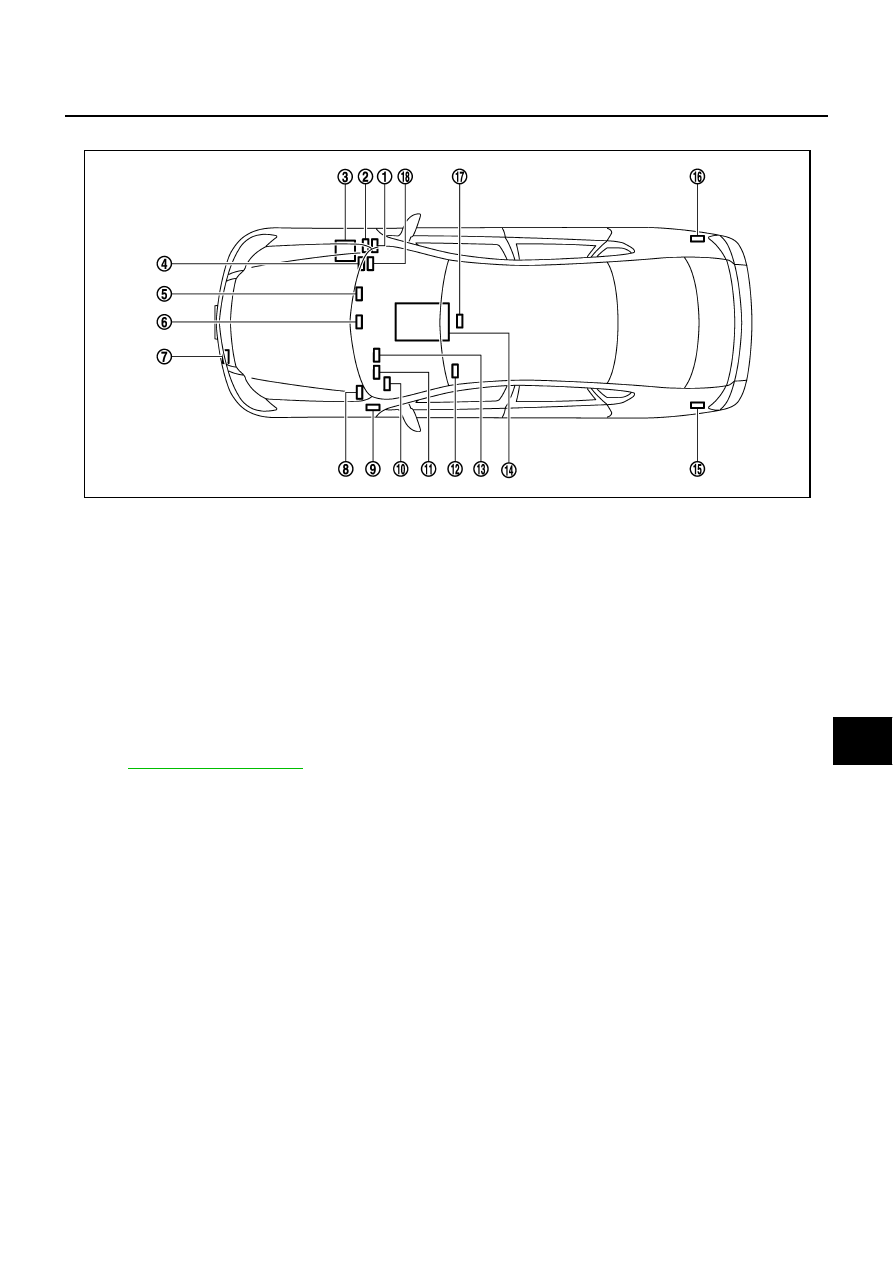
Component Parts Location

NKS004G4

Harness Layout

NKS004G5

Refer to 

PG-62, "Harness Layout"

 .

1.

AWD control unit F109

2.

AFS control unit F110

3.

IPDM E/R E9 

4.

BCM M1

5.

NAVI control unit M210: With 
navigation system
AV control unit M210: Without 
navigation system

6.

Unified meter and A/C amp.  M65

7.

ICC sensor integrated unit E61

8.

ABS actuator and electric unit 
(control unit) E30

9.

Intelligent Key unit M32

10. Data link connector M60

11. Low tire pressure warning con-

trol unit M19

12. Driver seat control unit B204

13. Steering angle sensor M47

14. TCM F42

15. Pre-crash seat belt control unit 

B142

16. RAS control unit B476

17. LDW camera unit M182

18. ECM M71

PKID0344E

LAN-82

[CAN]

TROUBLE DIAGNOSIS

Malfunction Area Chart

NKS004G6

MAIN LINE

BRANCH LINE

SHORT CIRCUIT

Malfunction Area

Reference

Main line between TCM and data link connector

LAN-83, "Main Line Between TCM and Data Link Connector"

Main line between data link connector and pre-crash seat belt 
control unit

LAN-84, "Main Line Between Data Link Connector and Pre-
crash Seat Belt Control Unit"

Main line between data link connector and RAS control unit

LAN-85, "Main Line Between Data Link Connector and RAS 
Control Unit"

Main line between RAS control unit and pre-crash seat belt con-
trol unit

LAN-86, "Main Line Between RAS Control Unit and Pre-crash 
Seat Belt Control Unit"

Main line between pre-crash seat belt control unit and driver 
seat control unit

LAN-87, "Main Line Between Pre-crash Seat Belt Control Unit 
and Driver Seat Control Unit"

Main line between driver seat control unit and ABS actuator and 
electric unit (control unit)

LAN-88, "Main Line Between Driver Seat Control Unit and ABS 
Actuator and Electric Unit (Control Unit)"

Main line between ABS actuator and electric unit (control unit) 
and ICC sensor integrated unit

LAN-89, "Main Line Between ABS Actuator and Electric Unit 
(Control Unit) and ICC Sensor Integrated Unit"

Malfunction Area

Reference

ECM branch line circuit

LAN-89, "ECM Branch Line Circuit"

AWD control unit branch line circuit

LAN-90, "AWD Control Unit Branch Line Circuit"

AFS control unit branch line circuit

LAN-91, "AFS Control Unit Branch Line Circuit"

BCM branch line circuit

LAN-91, "BCM Branch Line Circuit"

LDW camera unit branch line circuit

LAN-92, "LDW Camera Unit Branch Line Circuit"

TCM branch line circuit

LAN-93, "TCM Branch Line Circuit"

NAVI control unit branch line circuit

LAN-93, "NAVI Control Unit Branch Line Circuit"

AV control unit branch line circuit

LAN-94, "AV Control Unit Branch Line Circuit"

Data link connector branch line circuit

LAN-95, "Data Link Connector Branch Line Circuit"

Intelligent Key unit branch line circuit

LAN-95, "Intelligent Key Unit Branch Line Circuit"

Unified meter and A/C amp. branch line circuit

LAN-96, "Unified Meter and A/C Amp. Branch Line Circuit"

Steering angle sensor branch line circuit

LAN-97, "Steering Angle Sensor Branch Line Circuit"

Low tire pressure warning control unit branch line circuit

LAN-97, "Low Tire Pressure Warning Control Unit Branch Line 
Circuit"

RAS control unit branch line circuit

LAN-98, "RAS Control Unit Branch Line Circuit"

Pre-crash seat belt control unit branch line circuit

LAN-99, "Pre-Crash Seat Belt Control Unit Branch Line Circuit"

Driver seat control unit branch line circuit

LAN-99, "Driver Seat Control Unit Branch Line Circuit"

ABS actuator and electric unit (control unit) branch line circuit

LAN-100, "ABS Actuator and Electric Unit (Control Unit) Branch 
Line Circuit"

ICC sensor integrated unit branch line circuit

LAN-101, "ICC Sensor Integrated Unit Branch Line Circuit"

IPDM E/R branch line circuit

LAN-101, "IPDM E/R Branch Line Circuit"

Malfunction Area

Reference

CAN communication circuit

LAN-102, "CAN Communication Circuit"

TROUBLE DIAGNOSIS

LAN-83

[CAN]

C

D

E

F

G

H

I

J

L

M

A

B

LAN

Main Line Between TCM and Data Link Connector

NKS004G7

INSPECTION PROCEDURE

1. 

CHECK CONNECTOR

1.

Turn the ignition switch OFF.

2.

Disconnect the battery cable from the negative terminal.

3.

Check the following terminals and connectors for damage, bend and loose connection (connector side
and harness side).

Harness connector M61

Harness connector M62

OK or NG

OK

>> GO TO 2.

NG

>> Repair the terminal and connector.

2. 

CHECK HARNESS CONTINUITY (OPEN CIRCUIT)

1.

Disconnect the following harness connectors.

Harness connectors F102 and M72

Harness connectors M61 and M62

2.

Check the continuity between harness connectors.

OK or NG

OK

>> GO TO 3.

NG

>> Repair the main line between the harness connector M72 and M61.

3. 

CHECK HARNESS CONTINUITY (OPEN CIRCUIT)

Check the continuity between the harness connector and the data link connector.

OK or NG

OK

>>

Present error: Check the following items again.

Decision of CAN system type.

Not received CONSULT-II data (SELECT SYSTEM, SELF-DIAG RESULTS, CAN DIAG SUP-
PORT MNTR).

Procedure for detecting root cause.

Past error: Error was detected in the main line between the TCM and the data link connector. 

NG

>> Repair the main line between the harness connector M62 and the data link connector.

Harness connector

Harness connector

Continuity

Connector No.

Terminal No.

Connector No.

Terminal No.

M72

43H

M61

1

Yes

42H

2

Yes

Harness connector

Data link connector

Continuity

Connector No.

Terminal No.

Connector No.

Terminal No.

M62

1

M60

6

Yes

2

14

Yes

LAN-84

[CAN]

TROUBLE DIAGNOSIS

Main Line Between Data Link Connector and Pre-crash Seat Belt Control Unit

NKS004GY

INSPECTION PROCEDURE

1. 

CHECK CONNECTOR

1.

Turn the ignition switch OFF.

2.

Disconnect the battery cable from the negative terminal.

3.

Check the following terminals and connectors for damage, bend and loose connection (connector side
and harness side).

Harness connector M66

Harness connector B418

Harness connector B437

Harness connector B67

OK or NG

OK

>> GO TO 2.

NG

>> Repair the terminal and connector.

2. 

CHECK HARNESS CONTINUITY (OPEN CIRCUIT)

1.

Disconnect the harness connectors M66 and B418.

2.

Check the continuity between the data link connector and the harness connector.

OK or NG

OK

>> GO TO 3.

NG

>> Repair the main line between the data link connector and the harness connector M66.

3. 

CHECK HARNESS CONTINUITY (OPEN CIRCUIT)

1.

Disconnect the harness connectors B437 and B67.

2.

Check the continuity between harness connectors.

OK or NG

OK

>> GO TO 4.

NG

>> Replace the body No. 2 harness.

Data link connector

Harness connector

Continuity

Connector No.

Terminal No.

Connector No.

Terminal No.

M60

6

M66

38P

Yes

14

39P

Yes

Harness connector

Harness connector

Continuity

Connector No.

Terminal No.

Connector No.

Terminal No.

B418

38P

B437

1

Yes

39P

12

Yes


Content   ..  856  857  858  859   ..