Infiniti M35/M45 Y50. Manual - part 683
DTC P1140, P1145 IVT CONTROL POSITION SENSOR
EC-1205
[VK45DE]
C
D
E
F
G
H
I
J
K
L
M
A
EC
Specification data are reference values and are measured between each terminal and ground.
Pulse signal is measured by CONSULT-II.
CAUTION:
Do not use ECM ground terminals when measuring input/output voltage. Doing so may result in dam-
age to the ECM's transistor. Use a ground other than ECM terminals, such as the ground.
: Average voltage for pulse signal (Actual pulse signal can be confirmed by oscilloscope.)
TER-
MINAL
NO.
WIRE
COLOR
ITEM
CONDITION
DATA (DC Voltage)
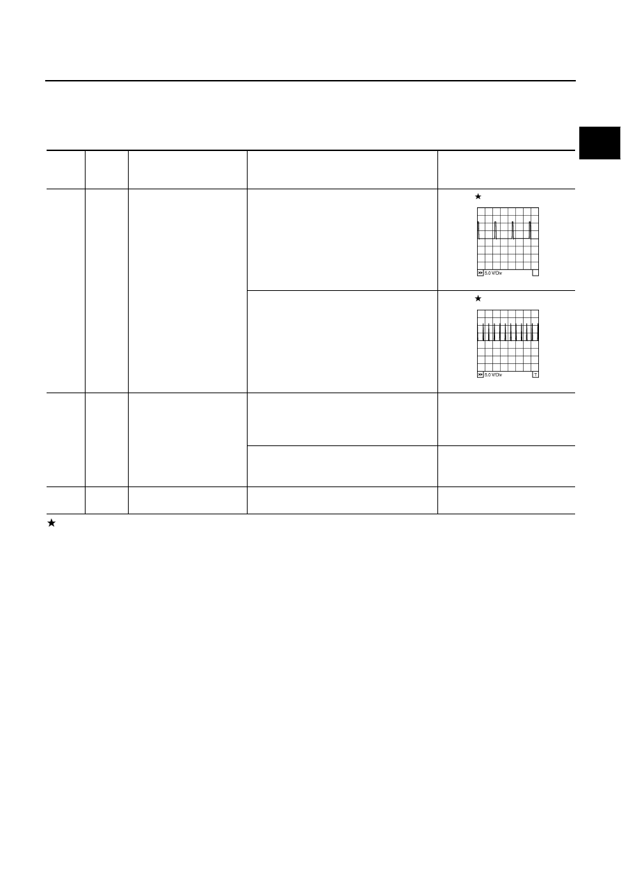
72
L
Intake valve timing control
position sensor (bank 1)
[Engine is running]
●
Warm-up condition
●
Idle speed
0 - 1.0V
[Engine is running]
●
Engine speed: 2,000rpm
0 - 1.0V
111
SB
ECM relay
(Self shut-off)
[Engine is running]
[Ignition switch: OFF]
●
For a few seconds after turning ignition
switch OFF
0 - 1.5V
[Ignition switch: OFF]
●
More than a few seconds after turning igni-
tion switch OFF
BATTERY VOLTAGE
(11 - 14V)
119
120
R
R
Power supply for ECM
[Ignition switch: ON]
BATTERY VOLTAGE
(11 - 14V)
PBIB2734E
PBIB2735E