Infiniti M35/M45 Y50. Manual - part 540
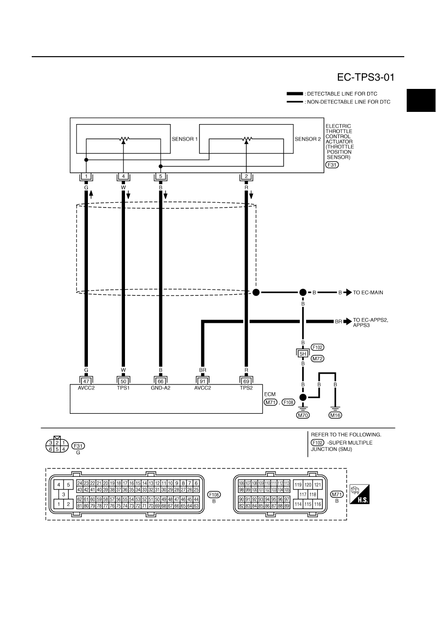
DTC P2135 TP SENSOR
EC-633
[VQ35DE]
C
D
E
F
G
H
I
J
K
L
M
A
EC
Wiring Diagram
NBS00575
TBWT1483E
|
|
|
DTC P2135 TP SENSOR EC-633 [VQ35DE] C D E F G H I J K L M A EC Wiring Diagram NBS00575 TBWT1483E |