Infiniti M35/M45 Y50. Manual - part 511


  Index      Infiniti     Infiniti M35/M45 Y50 - service repair manual 2007 year


Search            copyright infringement  


Content   ..  509  510  511  512   ..


Infiniti M35/M45 Y50. Manual - part 511


DTC P1220 FUEL PUMP CONTROL MODULE (FPCM)

EC-517

[VQ35DE]

C

D

E

F

G

H

I

J

K

L

M

A

EC

12. 

CHECK INTERMITTENT INCIDENT

Refer to 

EC-153, "TROUBLE DIAGNOSIS FOR INTERMITTENT INCIDENT"

 .

>> INSPECTION END

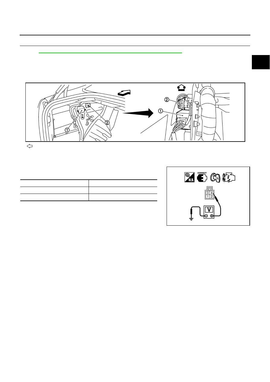
Component Inspection

NBS0053G

FUEL PUMP CONTROL MODULE

1.

Start engine and warm it up to normal operating temperature.

2.

Turn ignition switch OFF and wait at least 10 seconds.

3.

Check voltage between FPCM terminal 4 and ground under the
following conditions.

4.

If NG, replace fuel pump control module.

: Vehicle front

1.

FPCM

2.

Dropping resistor

Condition

Voltage

When engine cranking

Approx. 0V

After starting engine

Approx. 5V

PBIB2708E

PBIB0101E

EC-518

[VQ35DE]

DTC P1225 TP SENSOR

DTC P1225 TP SENSOR

PFP:16119

Component Description

NBS0053H

Electric throttle control actuator consists of throttle control motor,
throttle position sensor, etc. The throttle position sensor responds to
the throttle valve movement.
The throttle position sensor has the two sensors. These sensors are
a kind of potentiometers which transform the throttle valve position
into output voltage, and emit the voltage signal to the ECM. In addi-
tion, these sensors detect the opening and closing speed of the
throttle valve and feed the voltage signals to the ECM. The ECM
judges the current opening angle of the throttle valve from these sig-
nals and the ECM controls the throttle control motor to make the
throttle valve opening angle properly in response to driving condi-
tion.

On Board Diagnosis Logic

NBS0053I

The MIL will not light up for this diagnosis.

DTC Confirmation Procedure

NBS0053J

NOTE:
If DTC Confirmation Procedure has been previously conducted, always turn ignition switch OFF and wait at
least 10 seconds before conducting the next test.
TESTING CONDITION:
Before performing the following procedure, confirm that battery voltage is more than 10V at idle.

 WITH CONSULT-II

1.

Turn ignition switch ON.

2.

Select “DATA MONITOR” mode with CONSULT-II.

3.

Turn ignition switch OFF, wait at least 10 seconds.

4.

Turn ignition switch ON.

5.

If 1st trip DTC is detected, go to 

EC-519, "Diagnostic Procedure"

.

 WITH GST

Follow the procedure “WITH CONSULT-II” above.

PBIB0145E

DTC No.

Trouble diagnosis name

DTC detecting condition

Possible cause

P1225
1225

Closed throttle position 
learning performance

Closed throttle position learning value is exces-
sively low.

Electric throttle control actuator
(TP sensor 1 and 2)

SEF058Y

DTC P1225 TP SENSOR

EC-519

[VQ35DE]

C

D

E

F

G

H

I

J

K

L

M

A

EC

Diagnostic Procedure

NBS0053K

1. 

CHECK ELECTRIC THROTTLE CONTROL ACTUATOR VISUALLY

1.

Turn ignition switch OFF.

2.

Remove the intake air duct.

3.

Check if foreign matter is caught between the throttle valve and
the housing.

OK or NG

OK

>> GO TO 2.

NG

>> Remove the foreign matter and clean the electric throttle

control actuator inside.

2. 

REPLACE ELECTRIC THROTTLE CONTROL ACTUATOR

1.

Replace the electric throttle control actuator.

2.

Perform 

EC-86, "Throttle Valve Closed Position Learning"

 .

3.

Perform 

EC-86, "Idle Air Volume Learning"

 .

>> INSPECTION END

Removal and Installation

NBS0053L

ELECTRIC THROTTLE CONTROL ACTUATOR

Refer to 

EM-21, "INTAKE MANIFOLD COLLECTOR"

 .

PBIB1556E

EC-520

[VQ35DE]

DTC P1226 TP SENSOR

DTC P1226 TP SENSOR

PFP:16119

Component Description

NBS0053M

Electric throttle control actuator consists of throttle control motor,
throttle position sensor, etc. The throttle position sensor responds to
the throttle valve movement. 
The throttle position sensor has the two sensors. These sensors are
a kind of potentiometers which transform the throttle valve position
into output voltage, and emit the voltage signal to the ECM. In addi-
tion, these sensors detect the opening and closing speed of the
throttle valve and feed the voltage signals to the ECM. The ECM
judges the current opening angle of the throttle valve from these sig-
nals and the ECM controls the throttle control motor to make the
throttle valve opening angle properly in response to driving condi-
tion.

On Board Diagnosis Logic

NBS0053N

The MIL will not light up for this diagnosis.

DTC Confirmation Procedure

NBS0053O

NOTE:
If DTC Confirmation Procedure has been previously conducted, always turn ignition switch OFF and wait at
least 10 seconds before conducting the next test.
TESTING CONDITION:
Before performing the following procedure, confirm that battery voltage is more than 10V at idle.

 WITH CONSULT-II

1.

Turn ignition switch ON.

2.

Select “DATA MONITOR” mode with CONSULT-II.

3.

Turn ignition switch OFF, wait at least 10 seconds.

4.

Turn ignition switch ON.

5.

Repeat steps 3 and 4 for 32 times.

6.

If 1st trip DTC is detected, go to 

EC-521, "Removal and Installa-

tion"

 .

 WITH GST

Follow the procedure “WITH CONSULT-II” above.

PBIB0145E

DTC No.

Trouble diagnosis name

DTC detecting condition

Possible cause

P1226
1226

Closed throttle position 
learning performance

Closed throttle position learning is not per-
formed successfully, repeatedly.

Electric throttle control actuator
(TP sensor 1 and 2)

SEF058Y


Content   ..  509  510  511  512   ..