Infiniti M35/M45 Y50. Manual - part 464


  Index      Infiniti     Infiniti M35/M45 Y50 - service repair manual 2007 year


Search            copyright infringement  


Content   ..  462  463  464  465   ..


Infiniti M35/M45 Y50. Manual - part 464


DTC P0172, P0175 FUEL INJECTION SYSTEM FUNCTION

EC-329

[VQ35DE]

C

D

E

F

G

H

I

J

K

L

M

A

EC

8. 

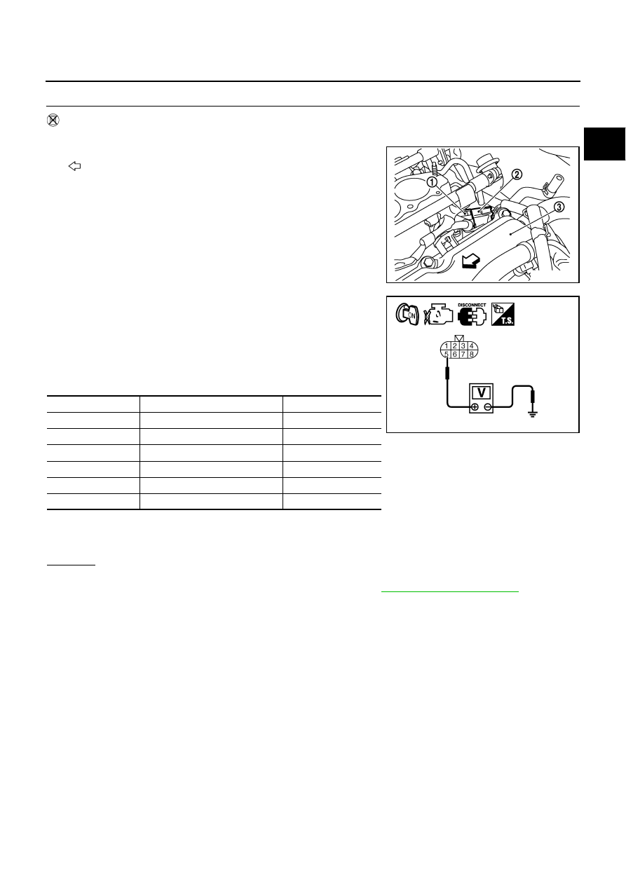
CHECK FUNCTION OF FUEL INJECTOR-I

 Without CONSULT-II

1.

Turn ignition switch OFF.

2.

Disconnect harness connectors F221 (1), F33 (2).

: vehicle front

Cylinder head (bank 2) (3)

3.

Turn ignition switch ON.

4.

Check voltage between harness connector F33 terminal 5 and
ground with CONSULT-II or tester.

5.

Turn ignition switch OFF.

6.

Disconnect ECM harness connector.

7.

Check harness continuity between the following terminals.

8.

Also check harness for short to ground and short to power.

OK or NG

OK

>> GO TO 9.

NG

>> Perform trouble diagnosis for FUEL INJECTOR, refer to 

EC-669, "FUEL INJECTOR"

 .

PBIB2785E

Voltage: Battery voltage

Cylinder

Harness connector F33 terminal

ECM terminal

1

6

23

2

4

42

3

2

22

4

3

41

5

1

21

6

7

40

Continuity should exist.

PBIB2323E

EC-330

[VQ35DE]

DTC P0172, P0175 FUEL INJECTION SYSTEM FUNCTION

9. 

CHECK FUNCTION OF FULE INJECTOR-II

Provide battery voltage between the following terminals, and then
interrupt it. Listen to each fuel injector operating sound.

OK or NG

OK

>> GO TO 10.

NG

>> Perform trouble diagnosis for FUEL INJECTOR, refer to 

EC-669, "FUEL INJECTOR"

 .

10. 

CHECK FUEL INJECTOR

1.

Remove fuel injector assembly. Refer to 

EM-47, "FUEL INJECTOR AND FUEL TUBE"

 .

Keep fuel hose and all fuel injectors connected to fuel tube.

2.

Confirm that the engine is cooled down and there are no fire hazards near the vehicle.

3.

Reconnect all harness connectors disconnected.

4.

Disconnect all fuel injector harness connectors.

5.

Disconnect all ignition coil harness connectors.

6.

Prepare pans or saucers under each fuel injectors.

7.

Crank engine for about 3 seconds.
Make sure fuel does not drip from fuel injector.

OK or NG

OK (Does not drip.)>>GO TO 11.
NG (Drips.)>>Replace the fuel injectors from which fuel is dripping. Always replace O-ring with new one. 

11. 

CHECK INTERMITTENT INCIDENT

Refer to 

EC-153, "TROUBLE DIAGNOSIS FOR INTERMITTENT INCIDENT"

 .

>> INSPECTION END

Cylinder

Harness connector F221 terminal

(+)

(–)

1

5

6

2

4

3

2

4

3

5

1

6

7

Operating sound should exist.

PBIB2497E

DTC P0181 FTT SENSOR

EC-331

[VQ35DE]

C

D

E

F

G

H

I

J

K

L

M

A

EC

DTC P0181 FTT SENSOR

PFP:22630

Component Description

NBS004Y0

The fuel tank temperature sensor (3) is used to detect the fuel tem-
perature inside the fuel tank. The sensor modifies a voltage signal
from the ECM. The modified signal returns to the ECM as the fuel
temperature input. The sensor uses a thermistor which is sensitive to
the change in temperature. The electrical resistance of the ther-
mistor decreases as temperature increases.

Fuel level sensor unit and fuel pump (1)

Fuel pressure regulator (2)

<Reference data>

*: This data is reference value and is measured between ECM terminal 107 (Fuel
tank temperature sensor) and ground.

CAUTION:

Do not use ECM ground terminals when measuring input/output
voltage. Doing so may result in damage to the ECM's transistor.
Use a ground other than ECM terminals, such as the ground.

On Board Diagnosis Logic

NBS004Y1

DTC Confirmation Procedure

NBS004Y2

NOTE:
If DTC Confirmation Procedure has been previously conducted, always turn ignition switch OFF and wait at
least 10 seconds before conducting the next test.

 WITH CONSULT-II

1.

Turn ignition switch ON.

2.

Select “DATA MONITOR” mode with CONSULT-II.

3.

Wait at least 10 seconds.
If the result is NG, go to 

EC-334, "Diagnostic Procedure"

 .

If the result is OK, go to following step.

4.

Check “COOLAN TEMP/S” value.
If “COOLAN TEMP/S” is less than 60

°

C (140

°

F), the result will

be OK.
If “COOLAN TEMP/S” is above 60

°

C (140

°

F), go to the following

step.

5.

Cool engine down until “COOLAN TEMP/S” is less than 60

°

C

(140

°

F).

6.

Wait at least 10 seconds.

7.

If 1st trip DTC is detected, go to 

EC-334, "Diagnostic Procedure"

 .

PBIB2707E

Fluid temperature

°

C (

°

F)

Voltage*

V

Resistance

k

20 (68)

3.5

2.3 - 2.7

50 (122)

2.2

0.79 - 0.90

SEF012P

DTC No.

Trouble diagnosis name

DTC detecting condition

Possible cause

P0181
0181

Fuel tank temperature 
sensor circuit range/
performance

Rationally incorrect voltage from the sensor is 
sent to ECM, compared with the voltage sig-
nals from engine coolant temperature sensor 
and intake air temperature sensor.

Harness or connectors
(The sensor circuit is open or shorted)

Fuel tank temperature sensor

SEF174Y

EC-332

[VQ35DE]

DTC P0181 FTT SENSOR

 WITH GST

Follow the procedure “WITH CONSULT-II” above.


Content   ..  462  463  464  465   ..