Infiniti M35/M45 Y50. Manual - part 424
DTC P0011, P0021 IVT CONTROL
EC-169
[VQ35DE]
C
D
E
F
G
H
I
J
K
L
M
A
EC
6.
CHECK TIMING CHAIN INSTALLATION
Check service records for any recent repairs that may cause timing chain misaligned.
Yes or No
Yes
>> Check timing chain installation. Refer to
.
No
>> GO TO 7.
7.
CHECK LUBRICATION CIRCUIT
Refer to
EM-93, "Inspection of Camshaft Sprocket (INT) Oil Groove"
.
OK or NG
OK
>> GO TO 8.
NG
>> Clean lubrication line.
8.
CHECK INTERMITTENT INCIDENT
Refer to
EC-153, "TROUBLE DIAGNOSIS FOR INTERMITTENT INCIDENT"
for CKP sensor (POS) and
>> INSPECTION END
Component Inspection
NBS004TY
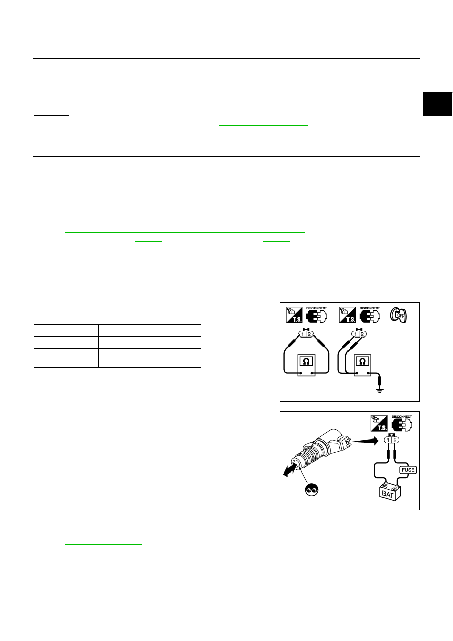
INTAKE VALVE TIMING CONTROL SOLENOID VALVE
1.
Disconnect intake valve timing control solenoid valve harness connector.
2.
Check resistance between intake valve timing control solenoid
valve terminals as follows.
If NG, replace intake valve timing control solenoid valve.
If OK, go to next step.
3.
Remove intake valve timing control solenoid valve.
4.
Provide 12V DC between intake valve timing control solenoid
valve terminals and then interrupt it. Make sure that the plunger
moves as shown in the figure.
CAUTION:
Do not apply 12V DC continuously for 5 seconds or more.
Doing so may result in damage to the coil in intake valve
timing control solenoid valve.
If NG, replace intake valve timing control solenoid valve.
NOTE:
Always replace O-ring when intake valve timing control
solenoid valve is removed.
Removal and Installation
NBS004TZ
INTAKE VALVE TIMING CONTROL SOLENOID VALVE
Refer to
Are there any service records that may cause timing chain misaligned?
Terminals
Resistance
1 and 2
7.0 - 7.5
Ω
[at 20
°
C (68
°
F)]
1 or 2 and ground
∞Ω
(Continuity should not exist)
PBIB0193E
PBIB2275E