Infiniti M35/M45 Y50. Manual - part 415


  Index      Infiniti     Infiniti M35/M45 Y50 - service repair manual 2007 year


Search            copyright infringement  


Content   ..  413  414  415  416   ..


Infiniti M35/M45 Y50. Manual - part 415


TROUBLE DIAGNOSIS

EC-133

[VQ35DE]

C

D

E

F

G

H

I

J

K

L

M

A

EC

*: Leaving cooling fan OFF with CONSULT-II while engine is running may cause the engine to overheat.

DTC & SRT CONFIRMATION MODE
SRT STATUS Mode

For details, refer to 

EC-60, "SYSTEM READINESS TEST (SRT) CODE"

 .

SRT WORK SUPPORT Mode

This mode enables a technician to drive a vehicle to set the SRT while monitoring the SRT status.

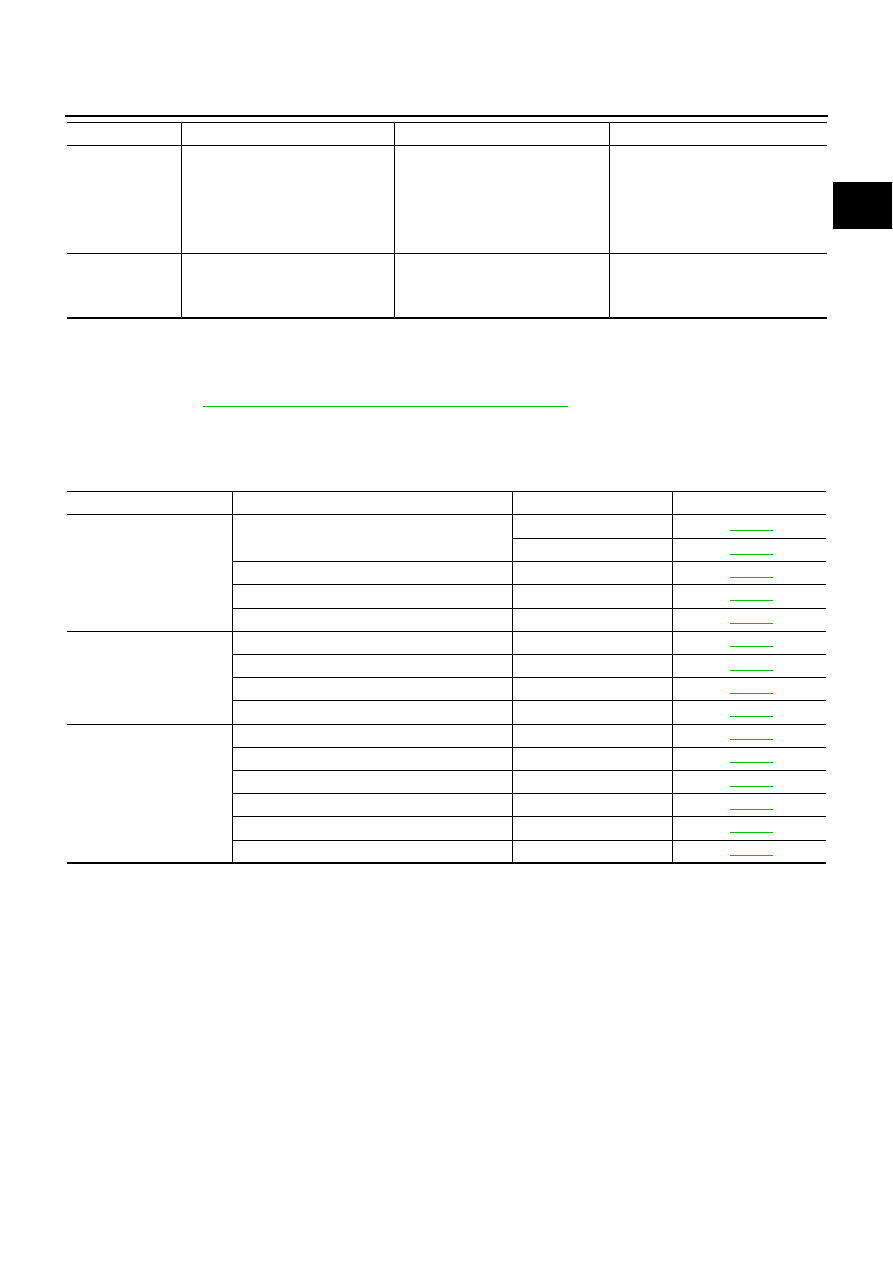
DTC WORK SUPPORT Mode

*: DTC P1442 and P1456 does not apply to Y50 models but appears in DTC Work Support Mode screens.

FAN DUTY CON-
TROL*

Ignition switch: ON

Change duty ratio using CON-
SULT-II.

Cooling fan speed changes.

Harness and connectors

Cooling fan motor

Cooling fan relay

Cooling fan control module

IPDM E/R

ALTERNATOR 
DUTY

Engine: Idle

Change duty ratio using CON-
SULT-II.

Battery voltage changes.

Harness and connectors

IPDM E/R

Alternator

TEST ITEM

CONDITION

JUDGEMENT

CHECK ITEM (REMEDY)

Test mode

Test item

Corresponding DTC No.

Reference page

EVAPORATIVE SYSTEM

EVP SML LEAK P0442/P1442*

P0442

EC-391

P0455

EC-445

EVP V/S LEAK P0456/P1456*

P0456

EC-453

PURG VOL CN/V P1444

P0443

EC-400

PURG FLOW P0441

P0441

EC-386

A/F SEN1

A/F SEN1 (B1) P1278/P1279

P0133

EC-262

A/F SEN1 (B1) P1276

P0130

EC-234

A/F SEN1 (B2) P1288/P1289

P0153

EC-262

A/F SEN1 (B2) P1286

P0150

EC-234

HO2S2

HO2S2 (B1) P1146

P0138

EC-285

HO2S2 (B1) P1147

P0137

EC-274

HO2S2 (B1) P0139

P0139

EC-298

HO2S2 (B2) P1166

P0158

EC-285

HO2S2 (B2) P1167

P0157

EC-274

HO2S2 (B2) P0159

P0159

EC-298

EC-134

[VQ35DE]

TROUBLE DIAGNOSIS

REAL TIME DIAGNOSIS IN DATA MONITOR MODE (RECORDING VEHICLE DATA)
Description

CONSULT-II has two kinds of triggers and they can be selected by touching “SETTING” in “DATA MONITOR”
mode.

1.

“AUTO TRIG” (Automatic trigger):

The malfunction will be identified on the CONSULT-II screen
in real time.
In other words, DTC/1st trip DTC and malfunction item will be
displayed if the malfunction is detected by ECM.
At the moment a malfunction is detected by ECM, “MONI-
TOR” in “DATA MONITOR” screen is changed to “Recording
Data ... xx%” as shown at right, and the data after the mal-
function detection is recorded. Then when the percentage
reached 100%, “REAL-TIME DIAG” screen is displayed. If
“STOP” is touched on the screen during “Recording Data ...
xx%”, “REAL-TIME DIAG” screen is also displayed.
The recording time after the malfunction detection and the
recording speed can be changed by “TRIGGER POINT” and
“Recording Speed”. Refer to CONSULT-II Operation Manual.

2.

“MANU TRIG” (Manual trigger):

DTC/1st trip DTC and malfunction item will not be displayed
automatically on CONSULT-II screen even though a malfunc-
tion is detected by ECM.
DATA MONITOR can be performed continuously even though
a malfunction is detected.

PBIB1593E

SEF707X

TROUBLE DIAGNOSIS

EC-135

[VQ35DE]

C

D

E

F

G

H

I

J

K

L

M

A

EC

Operation

1.

“AUTO TRIG”

While trying to detect the DTC/1st trip DTC by performing the “DTC Confirmation Procedure”, be sure
to select to “DATA MONITOR (AUTO TRIG)” mode. You can confirm the malfunction at the moment it is
detected.

While narrowing down the possible causes, CONSULT-II should be set in “DATA MONITOR (AUTO
TRIG)” mode, especially in case the incident is intermittent.
When you are inspecting the circuit by gently shaking (or twisting) the suspicious connectors, compo-
nents and harness in the “DTC Confirmation Procedure”, the moment a malfunction is found the DTC/
1st trip DTC will be displayed. (Refer to “INCIDENT SIMULATION TESTS” in 

GI-28, "How to Perform

Efficient Diagnosis for an Electrical Incident"

 .)

2.

“MANU TRIG”

If the malfunction is displayed as soon as “DATA MONITOR” is selected, reset CONSULT-II to “MANU
TRIG”. By selecting “MANU TRIG” you can monitor and store the data. The data can be utilized for fur-
ther diagnosis, such as a comparison with the value for the normal operating condition.

Generic Scan Tool (GST) Function

NBS004T8

DESCRIPTION

Generic Scan Tool (OBDII scan tool) complying with SAE J1978 has
8 different functions explained below.
ISO9141 is used as the protocol.
The name “GST” or “Generic Scan Tool” is used in this service man-
ual.

PBIB0197E

SEF139P

EC-136

[VQ35DE]

TROUBLE DIAGNOSIS

FUNCTION

INSPECTION PROCEDURE

1.

Turn ignition switch OFF.

2.

Connect “GST” to data link connector (1), which is located under
LH dash panel near the hood opener handle.

Diagnostic Service

Function

Service $01

READINESS TESTS

This diagnostic service gains access to current emission-related data values, including 
analog inputs and outputs, digital inputs and outputs, and system status information.

Service $02

(FREEZE DATA)

This diagnostic service gains access to emission-related data value which were stored by 
ECM during the freeze frame. For details, refer to 

EC-60, "FREEZE FRAME DATA AND 

1ST TRIP FREEZE FRAME DATA"

 .

Service $03

DTCs

This diagnostic service gains access to emission-related power train trouble codes which 
were stored by ECM.

Service $04

CLEAR DIAG INFO

This diagnostic service can clear all emission-related diagnostic information. This 
includes:

Clear number of diagnostic trouble codes (Service $01)

Clear diagnostic trouble codes (Service $03)

Clear trouble code for freeze frame data (Service $01)

Clear freeze frame data (Service $02)

Reset status of system monitoring test (Service $01)

Clear on board monitoring test results (Service $06 and $07)

Service $06

(ON BOARD TESTS)

This diagnostic service accesses the results of on board diagnostic monitoring tests of 
specific components/systems that are not continuously monitored.

Service $07

(ON BOARD TESTS)

This diagnostic service enables the off board test drive to obtain test results for emission-
related powertrain components/systems that are continuously monitored during normal 
driving conditions.

Service $08

This diagnostic service can close EVAP system in ignition switch ON position (Engine 
stopped). When this diagnostic service is performed, EVAP canister vent control valve 
can be closed.
In the following conditions, this diagnostic service cannot function.

Low ambient temperature

Low battery voltage

Engine running

Ignition switch OFF

Low fuel temperature

Too much pressure is applied to EVAP system

Service $09

(CALIBRATION ID)

This diagnostic service enables the off-board test device to request specific vehicle infor-
mation such as Vehicle Identification Number (VIN) and Calibration IDs.

PBIB2712E


Content   ..  413  414  415  416   ..