Index Infiniti Infiniti M35/M45 Y50 - service repair manual 2007 year
Search copyright infringement
Content .. 374 375 376 377 ..
Infiniti M35/M45 Y50. Manual - part 376
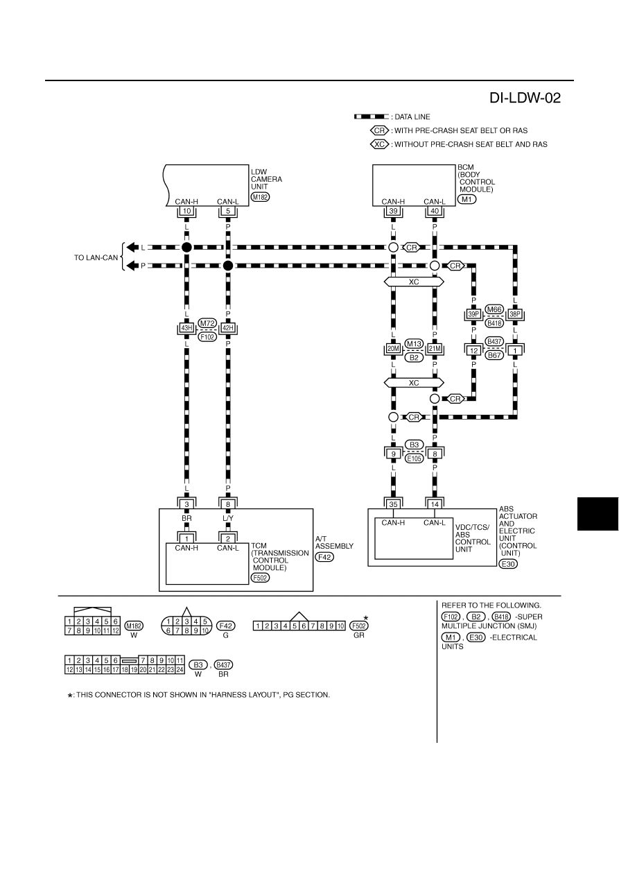
LANE DEPARTURE WARNING SYSTEM
DI-87
C
D
E
F
G
H
I
J
L
M
A
B
DI
TKWT5288E