Infiniti M35/M45 Y50. Manual - part 177


  Index      Infiniti     Infiniti M35/M45 Y50 - service repair manual 2007 year


Search            copyright infringement  


Content   ..  175  176  177  178   ..


Infiniti M35/M45 Y50. Manual - part 177


TERMINALS AND REFERENCE VALUE FOR CONTROL UNIT

AV-85

[WITHOUT MOBILE ENTERTAINMENT SYSTEM]

C

D

E

F

G

H

I

J

L

M

A

B

AV

26

(V/W)

Ground

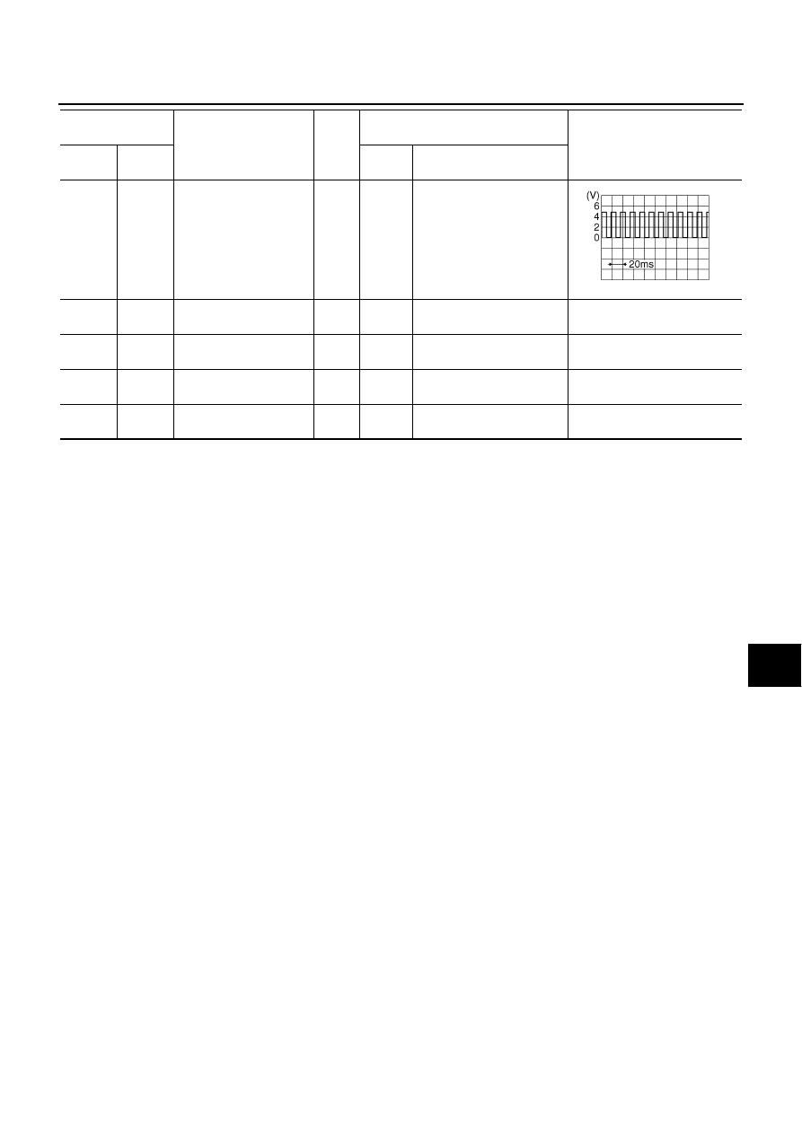
Vehicle speed signal
(8-pulse)

Input

ON

When vehicle speed is 
approx. 40 km/h (25 MPH).

29

(G/R)

Ground

Ignition signal

Input

ON

Battery voltage

30

(BR)

Ground

ACC power supply 

Input

ACC

Battery voltage

31

(B)

Ground

Ground

ON

Approx. 0 V

32

(BR/Y)

Ground

Battery power supply

Input

OFF

Battery voltage

Terminal

(Wire color)

Item

Signal

input/

output

Condition

Reference value

+

Ignition

switch

Operation

SKIA6649J

AV-86

[WITHOUT MOBILE ENTERTAINMENT SYSTEM]

DIAGNOSIS SYSTEM

DIAGNOSIS SYSTEM

PFP:00000

Multifunction Switch Self-Diagnosis Function

NKS0048T

It can check each switch ON/OFF (continuity) operation of centralized switches.

SELF-DIAGNOSIS MODE

Turn the ignition switch from OFF position to ACC position.
Within 10 seconds, press and hold BACK switch and 

 switch

for 3 seconds or more. Then, when these switches are released,
the buzzer sounds, all indicators of multifunction switch turned
on, and self-diagnosis mode is started.

When each switch is pressed, the switch continuity can be
checked by sounding the buzzer.

CAUTION:

The hazard switch cannot be checked.

FINISHING SELF-DIAGNOSIS MODE

When the ignition switch is turned ON, self-diagnosis mode is canceled.

Multi AV System Diagnosis Functions

NKS0048U

There are 2 diagnosis functions (On board diagnosis and diagnosis using CONSULT-II). It is necessary to
use them properly according to the condition. If the on board diagnosis starts, perform diagnosis with on
board diagnosis. If the on board diagnosis does not start (because the display is not displayed, the multi-
function switch operation is not activated, etc.), perform diagnosis using CONSULT-II.

At on board diagnosis, the AV (NAVI) control unit diagnosis function starts when multifunction switch oper-
ation and the AV (NAVI) control unit performs the diagnosis for each unit of system. Then, it displays the
results on the display.

At diagnosis using CONSULT-II, the AV (NAVI) control unit diagnosis function starts when the CAN com-
munication and the AV (NAVI) control unit perform the diagnosis for each unit of system.

On Board Diagnosis

NKS0048V

DESCRIPTION

It has Self-Diagnosis mode for conducting trouble diagnosis automatically and a Confirmation/Adjustment
mode for operating manually.

Self-diagnosis mode diagnoses AV (NAVI) control unit and communication of each unit composing sys-
tem, and displays self-diagnosis results. NAVI control unit diagnoses communication with GPS antenna
simultaneously.

Confirmation/Adjustment mode is used to monitor the vehicle signals requiring operation and judgement
by a technician (malfunctions that cannot be automatically judged by the system), the confirmation/
change/adjustment of setting value, the error history of system, and the communication condition of sys-
tem.

SKIB3979E

DIAGNOSIS SYSTEM

AV-87

[WITHOUT MOBILE ENTERTAINMENT SYSTEM]

C

D

E

F

G

H

I

J

L

M

A

B

AV

On Board Diagnosis Item

*1: With navigation system

*2: With rear view monitor

STARTING PROCEDURE

1.

Start the engine.

2.

Turn the audio system OFF.

3.

While pushing the “SETTING” button, turn the volume control
dial clockwise or counterclockwise for 40 clicks or more. (When
the self-diagnosis mode is started, a short beep will be heard.)

Shifting from current screen to previous screen is performed
by pushing “BACK” button.

Mode

Description

Self Diagnosis

AV (NAVI) control unit diagnosis and connection diagnosis between 
AV (NAVI) control unit and each unit

The DVD-ROM drive diagnosis of NAVI control unit and the connec-
tion diagnosis between NAVI control unit and GPS antenna can be 
performed
(DVD-ROM drive will not be diagnosed when no map DVD-ROM is in 
it.)

Confirmation/
Adjustment

Display Diagnosis

The tint can be confirmed by the color spectrum bar display. The shad-
ing of color can be confirmed by the gradation bar display.

Vehicle Signals

Diagnosis of signals can be performed for vehicle speed, parking brake, 
lights, ignition switch, and reverse.

Speaker Test

The connection of a speaker can be confirmed by test tone.

Climate Control

Start auto air conditioner system self-diagnosis.

Navigation

*1

Steering Angle 
Adjustment

When there is a difference between the actual turning angle and the 
vehicle mark turning angle, it can be adjusted.

Speed Calibration

When there is a difference between the current location mark and the 
actual location, it can be adjusted.

Error History

The system malfunction and the frequency when occurred in the past 
are displayed. When the malfunctioning item is selected, the time and 
place that the selected malfunction last occurred are displayed.

Synchronizer FES clock

-

Vehicle CAN Diagnosis

The transmitting/receiving of CAN communication can be monitored.

AV COMM Diagnosis

The communication condition of each unit of Multi AV system can be 
monitored.

Handsfree Phone

The received volume adjustment of hands-free phone, microphone 
speaker check, and erase memory can be performed.

Camera Cont.

*2

The signal connected to camera control unit can be checked and the 
guiding line position that overlaps rear view camera image can be 
adjusted.

Bluetooth

The passkey and the name of device can be checked and changed

Delete Unit Connection Log

Erase the connection history of unit and error history

SKIB3655E

AV-88

[WITHOUT MOBILE ENTERTAINMENT SYSTEM]

DIAGNOSIS SYSTEM

4.

The trouble diagnosis initial screen is displayed, and then the
items of “Self Diagnosis” and “Confirmation/Adjustment” can be
selected.

Self Diagnosis Mode

NKS0048W

1.

Start the diagnosis function, and then select “Self Diagnosis”.

Self-diagnosis subdivision screen will be shown and the opera-
tion will enter the self-diagnosis mode.

The bar graph visible on self-diagnosis screen displays progress
of the diagnosis.

2.

Diagnostic results are displayed when the self-diagnosis is com-
plete. Each unit name and connection lines between each unit
will be colored according to the diagnostic results, as follows.

Note: Only control unit (AV control unit, NAVI control unit) is displayed in red.

If multiple errors occur at the same time for a single unit, the screen switch colors are determined accord-
ing to the following order of priority: red > yellow > gray.

Select a switch on the “Diagnosis results” screen and comments
for the trouble diagnosis results will be shown.

SKIB3656E

SKIB3657E

Diagnosis results

Unit

Con-

nection 

line

Normal

Green

Green

Connection malfunction

Gray

Yellow

DVD-ROM drive undiagnosed

Gray

Green

DVD-ROM and DVD-ROM 
drive malfunction

Yellow

Green

Unit returned an error

Note

Red

Green

SKIB3980E

SKIB3659E


Content   ..  175  176  177  178   ..