Content .. 1022 1023 1024 1025 ..
Infiniti M35/M45 Y50. Manual - part 1024
REAR FINAL DRIVE ASSEMBLY
RFD-23
C
E
F
G
H
I
J
K
L
M
A
B
RFD
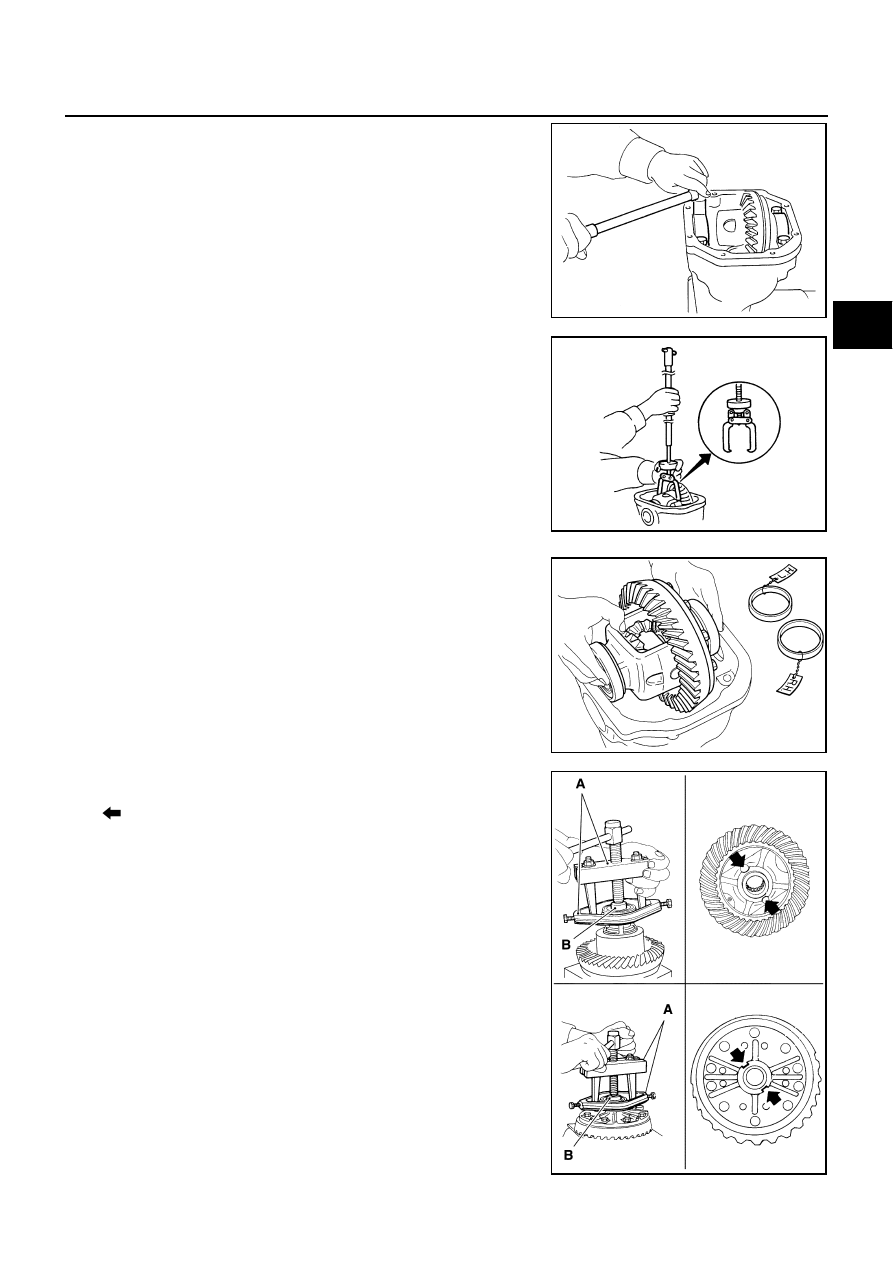
7.
Remove bearing caps.
8.
Lift differential case assembly out with a suitable tool.
●
Keep side bearing outer races together with inner race. Do
not mix them up.
Also, keep side bearing adjusting washers together with bear-
ings.
9.
Remove side bearing inner race.
To prevent damage to bearing, engage puller jaws in groove
(
).
CAUTION:
●
To prevent damage to the side bearing and drive gear,
place copper plates between these parts and vise.
●
It is not necessary to remove side bearing inner race
except it is replaced.
S-PD343
PDIA0547E
SPD527
Tool number
A: ST33051001 (J-22888-20)
B: ST33061000 (J-8107-2)
PDIA0758J