Infiniti F50. Manual - part 738
TOP TETHER STRAP CHILD RESTRAINT
SB-9
C
D
E
F
G
I
J
K
L
M
A
B
SB
TOP TETHER STRAP CHILD RESTRAINT
PFP:88000
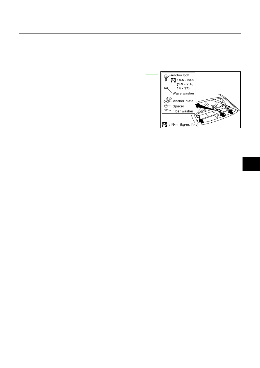
Removal and Installation
EHS00089
CAUTION:
Replace anchor bolts if they are deformed or worn out.
REMOVAL
1.
Remove the top tether strap child restraint cover. Refer to
2.
Remove the top tether strap child restraint.
INSTALLATION
To install, reverse the removal procedure sequence.
SHIA0164E