Infiniti F50. Manual - part 589


  Index      Infiniti     Infiniti F50 - service repair manual 2006 year


Search            


Content   ..  587  588  589  590   ..


Infiniti F50. Manual - part 589


POWER WINDOW SYSTEM

GW-27

C

D

E

F

G

H

J

K

L

M

A

B

GW

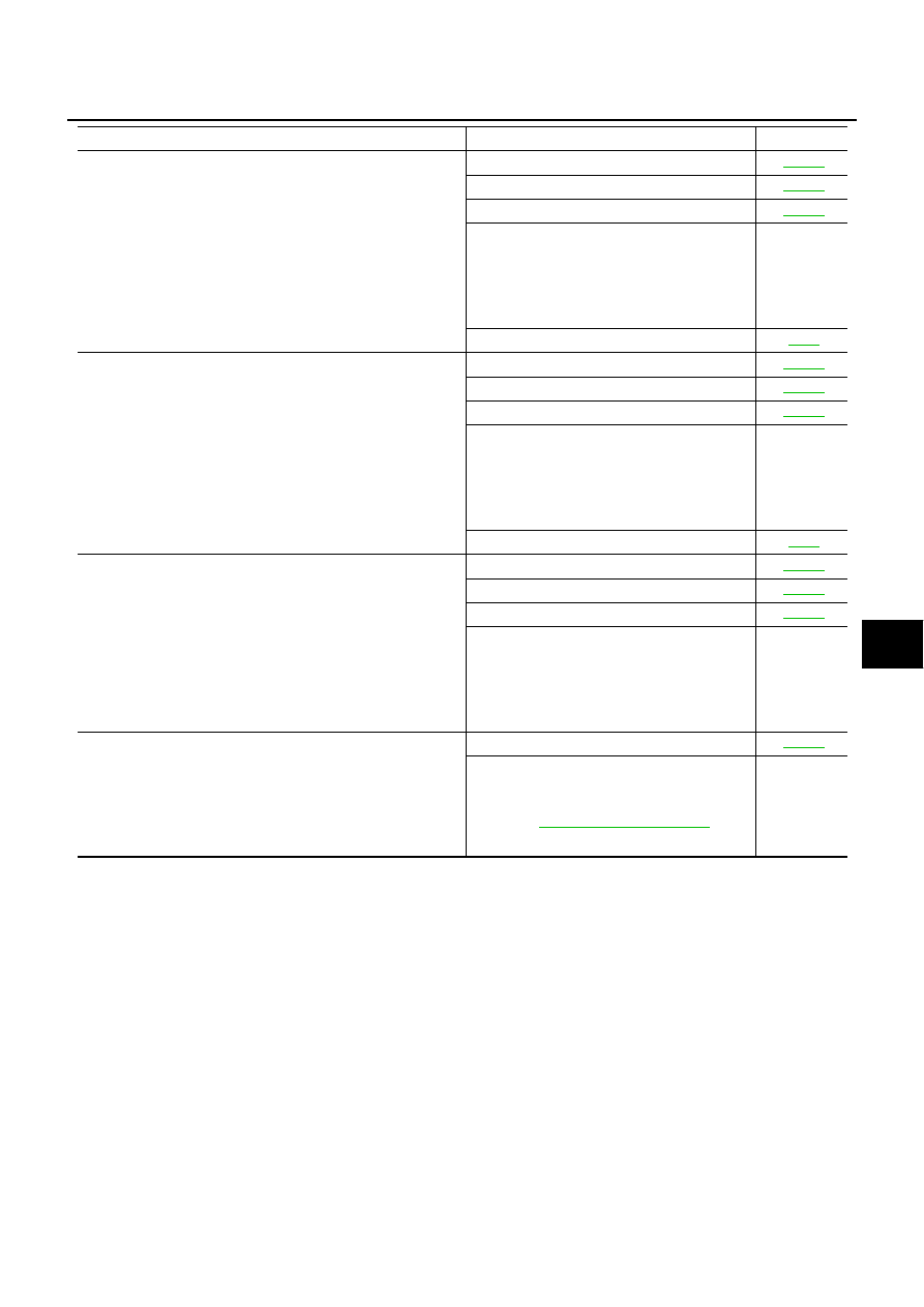
Anti-pinch system does not operate normally (driver side).

1. Limit switch is adjusted.

GW-53

2. Limit switch check (driver side)

GW-32

3. Encoder circuit check (driver side)

GW-36

4. Door window sliding part malfunction.

A foreign material adheres to window glass 
or glass run rubber.

Glass run rubber wear or deformation.

Sash is tilted too much, or not enough.

5. Replace driver door control unit (LCU1).

EI-30

Anti-pinch system does not operate normally (passenger side).

1. Limit switch is adjusted.

GW-53

2. Limit switch check (passenger side).

GW-33

3. Encoder circuit check (passenger side).

GW-37

4. Door window sliding part malfunction.

A foreign material adheres to window glass 
or glass run rubber.

Glass run rubber wear or deformation.

Sash is tilted too much, or not enough.

5. Replace passenger side door control unit.

EI-30

Anti-pinch system does not operate normally (rear RH or LH).

1. Limit switch is adjusted.

GW-56

2. Limit switch check (rear LH or RH).

GW-34

3. Encoder circuit check (rear LH or RH).

GW-39

4. Door window sliding part malfunction.

A foreign material adheres to window glass 
or glass run rubber.

Glass run rubber wear or deformation.

Sash is tilted too much, or not enough.

Power window timer function does not operate properly.

1. Door switch check.

GW-43

2. Check the following

harness for open and short between BCM 
and power window main switch (LCU01).
Refer to 

LAN-7, "On Board Diagnosis"

BCM

Symptom

Diagnostic procedure.

Refer page

GW-28

POWER WINDOW SYSTEM

Communication Signal Circuit Check

EIS000NX

1. 

CHECK COMMUNICATION CIRCUIT 

1.

Turn ignition switch OFF.

2.

Disconnect connectors for driver door control unit (LCU01) and malfunctioning door control unit.

3.

Check continuity between driver door control unit (LCU01) connector terminal 5 and malfunctioning door
control unit connector terminal 11.

4.

Check continuity between driver door control unit (LCU01) connector terminal 5 and ground.

OK or NG?

OK

>> GO TO 2

NG

>> Repair or replace harness

2. 

CHECK COMMUNICATION SIGNAL 

1.

Connect driver door control unit (LCU01) and malfunctioning door control unit connector.

2.

Check the signal between malfunctioning door control unit connector terminal 11 and ground with oscillo-
scope.

OK or NG?

OK

>> Communication signal is OK.

NG

>>

All door control unit (passenger, rear LH or RH) connected are NG.

 Replace driver door con-

trol unit (LCU01).

Any of door control unit (passenger, rear LH or RH) connected are NG.

 Replace malfunction-

ing door control unit.

Passenger door control unit

Terminals

Continuity

Driver door control unit

Passenger door control unit

Connector

Terminal

(Wire color)

Connector

Terminal

(Wire color)

D8

5 (G/OR)

D38

11 (G/OR)

Yes

Rear door control unit LH or RH

Terminals

Continuity

Driver door control unit

Rear LH or RH door control unit 

Connector

Terminal

(Wire color)

Connector

Terminal

(Wire color)

D8

5 (G/OR)

D58 (LH)

D78 (RH)

11 (G/OR)

Yes

 5 (G/OR) – Ground

: Continuity should not exist.

PIIB0301E

Passenger door control unit

Terminals

Signal

(+)

(–)

Connector

Terminal

(Wire color)

Ground

D38

11 (G/OR)

Rear LH, RH door control unit

Terminals

(+)

(–)

Connector

Terminal

(Wire color)

Ground

D58 (LH)

D78 (RH)

11 (G/OR)

PIIA2978E

SIIA0591J

POWER WINDOW SYSTEM

GW-29

C

D

E

F

G

H

J

K

L

M

A

B

GW

Front Power Window Regulator (driver side) Circuit Check

EIS000JB

1. 

CHECK DRIVER DOOR CONTROL UNIT OUTPUT SIGNAL 

1.

Turn ignition switch ON.

2.

Check voltage between front power window regulator (driver side) connector and ground.

OK or NG?

OK

>> Replace front power window motor (driver side).

NG

>> GO TO 2

2. 

CHECK DRIVER POWER WINDOW MOTOR CIRCUIT 

1.

Turn ignition switch OFF.

2.

Disconnect front power window regulator (driver side) connector and driver door control unit (LCU01) con-
nector.

3.

Check continuity between front power window regulator (driver side) connector D7 terminals 1, 2 and
driver door control unit (LCU01) connector D8 terminals 11, 18.

4.

Check continuity between front power window regulator (driver
side) connector D7 terminals 1, 2 and  ground.

OK or NG?

OK

>> Replace driver door control unit (LCU01).

NG

>> Repair or replace harness between driver door control

unit (LCU01) and front power window regulator (driver side).

Connector

Terminals (Wire color)

Condition

Voltage [V]

(Approx.)

(+)

(–)

D7

1 (L/W)

Ground

Window is 

closing

0

Window is 

opening

Battery voltage 

2 (L/R)

Window is 

closing

Battery voltage

Window is 

opening

0

PIIA2976E

 1 (L/W) – 11 (L/W)

: Continuity should exist.

 2 (L/R) – 18 (L/R)

: Continuity should exist.

 1 (L/W) – Ground

: Continuity should not exist.

 2 (L/R) – Ground

: Continuity should not exist.

PIIA2975E

GW-30

POWER WINDOW SYSTEM

Front Power Window Regulator (passenger side) Circuit Check

EIS000JD

1. 

CHECK PASSENGER DOOR CONTROL UNIT OUTPUT SIGNAL

1.

Turn ignition switch ON.

2.

Check voltage between front power window regulator (passenger side) connector and ground.

OK or NG?

OK

>> Replace front power window motor (passenger side).

NG

>> GO TO 2

2. 

CHECK FRONT POWER WINDOW REGULATOR (PASSENGER SIDE) CIRCUIT

1.

Turn ignition switch OFF.

2.

Disconnect front power window regulator (passenger side) and passenger door control unit connector.

3.

Check continuity between front power window regulator (passenger side) connector D37 terminals 1, 2
and passenger door control unit connector D39 terminals 4, 5.

4.

Check continuity between front power window regulator (pas-
senger side) connector D37 terminals 1, 2 and ground.

OK or NG?

OK

>> Replace passenger door control unit.

NG

>> Repair or replace harness between front power window

regulator (passenger side) and passenger door control unit.

Connector

Terminals (Wire color)

Condition

Voltage [V]

(Approx.)

(+)

(–)

D37

1 (L/W)

Ground

Window is 

closing

0

Window is 

opening

Battery voltage 

2 (L/R)

Window is

 closing

Battery voltage

Window is 

opening

0

PIIA2980E

1 (L/W) – 4 (L/W)

:Continuity should exist.

2 (L/R) – 5 (L/R)

:Continuity should exist.

1 (L/W) – Ground

:Continuity should not exist.

2 (L/R) – Ground

:Continuity should not exist.

PIIA2979E


Content   ..  587  588  589  590   ..