Infiniti F50. Manual - part 534
EXHAUST MANIFOLD AND THREE WAY CATALYST
EM-23
C
D
E
F
G
H
I
J
K
L
M
A
EM
e.
Remove exhaust manifold cover.
f.
Loosen nuts in reverse order of illustration to remove exhaust
manifold and three way catalyst.
CAUTION:
Disregard the numerical order No.9 to 12 in removal.
3.
Remove exhaust manifold and three way catalyst (right bank)
loosening nuts in reverse order in the figure.
a.
Remove drive belt and alternator with power tool. Refer to
19, "Removal and Installation"
.
b.
Remove exhaust front tube with power tool. Refer to
c.
Remove nuts on bottom of right engine mounting insulator, and
lift up right side of engine approximately 3 cm (1.18 in) with transmission jack.
d.
Remove starter motor with power tool. Refer to
SC-28, "Removal and Installation"
e.
Support and lift up bottom of engine with transmission jack. Remove right engine mount insulator along
with right engine mount brackets.
f.
Remove exhaust manifold cover.
g.
Loosen nuts in reverse order of illustration to remove exhaust manifold and three way catalyst with power
tool.
CAUTION:
Disregard the numerical order No.9 to 12 in removal.
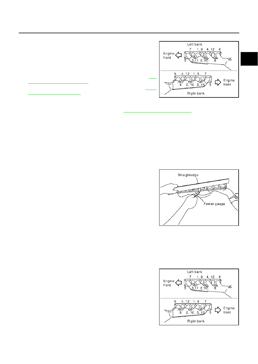
INSPECTION AFTER REMOVAL
Surface Distortion
Use a reliable straightedge and feeler gauge to check the flatness of
each exhaust manifold flange surface.
INSTALLATION
Install in the reverse order of removal paying attention to the following.
Exhaust Manifold Gasket
Install exhaust manifold gasket with its directional protrusion set upward. Refer to illustration of components
on former page.
Tightening Exhaust Manifold Nuts
●
Install exhaust manifold and three way catalyst in the numerical
order shown in the figure.
●
Tighten nuts No.1 to No.4 in two steps. Order No.9 to 12 shows
second step.
PBIC0022E
Limit
: 0.3mm (0.012in)
PBIC0023E
PBIC0022E