Infiniti F50. Manual - part 200
POWER DOOR LOCK SYSTEM
BL-47
C
D
E
F
G
H
J
K
L
M
A
B
BL
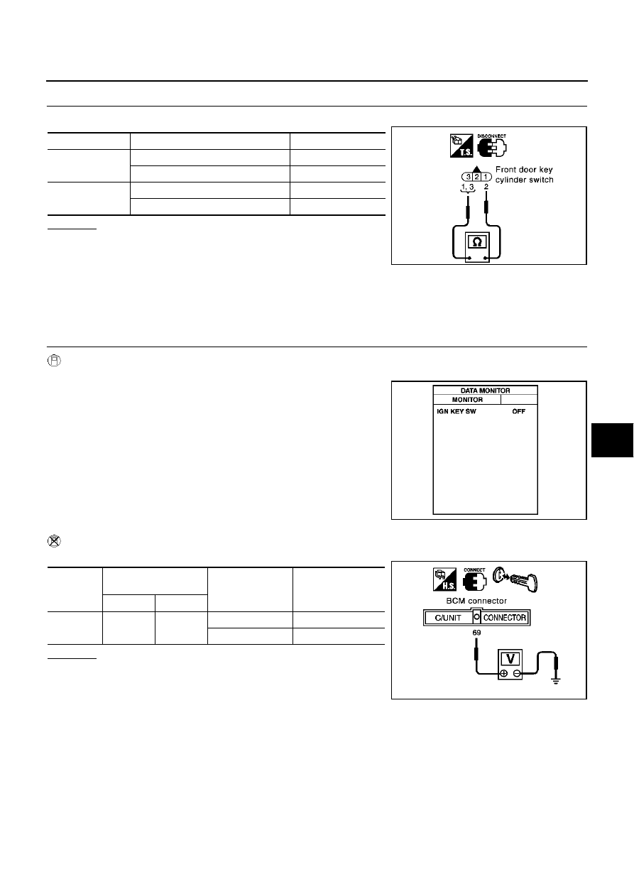
2.
CHECK DOOR KEY CYLINDER SWITCH
Check continuity between door key cylinder switch connector terminal.
OK or NG
OK
>> Check the following.
●
Harness between front key cylinder switch and driver
door control unit
●
Harness between front key cylinder switch and ground
NG
>> Replace front door key cylinder switch.
Check Key Switch
EIS003OE
1.
CHECK KEY SWITCH
With CONSULT-II
Check key switch “IGN KEY SW” in “DATA MONITOR” mode with CONSULT-II.
Without CONSULT-II
Check voltage between BCM connector M4 terminal 69 (PU/W) and ground.
OK or NG
OK
>> Key switch is OK.
NG
>> GO TO 2.
Terminals
Condition
Continuity
1 – 2
Key is turned to UNLOCK
Yes
Key is turned to LOCK or neutral.
No
2 – 3
Key is turned to LOCK.
Yes
Key is turned to UNLOCK or neutral.
No
PIIA3148E
Key is inserted in ignition
key cylinder
: IGN KEY SW ON
Key is removed from ignition
key cylinder
: IGN KEY SW OFF
PIIA4243E
Connector
Terminal
(Wire color)
Condition
Voltage (V)
(Approx.)
( + )
( – )
M4
69 (PU/W)
Ground
Key is inserted
Battery voltage
Key is removed
0
PIIA2820E