Infiniti F50. Manual - part 21
TROUBLE DIAGNOSIS FOR SELF-DIAGNOSTIC ITEMS
ACS-77
[ICC]
C
D
E
F
G
H
I
J
L
M
A
B
ACS
DTC 61 PRESS SEN CIRCUIT
EKS005QF
1.
CHECK CONNECTOR BRAKE PRESSURE SENSOR AND ICC UNIT
1.
Turn ignition switch OFF.
2.
Disconnect connectors of brake pressure sensor and ICC unit, and connect them securely again. Then
erase DTC. After that, perform self-diagnosis of ICC system again.
OK or NG
OK
>>
●
Poor connector connection
●
Check connector. (Check connector housing for disconnected, loose, bent, and collapsed ter-
minals. If any malfunction is detected, repair applicable part.) After repair, Erase DTC, and per-
form ICC system running test. Then perform self-diagnosis of ICC system again.
NG
>> GO TO 2.
2.
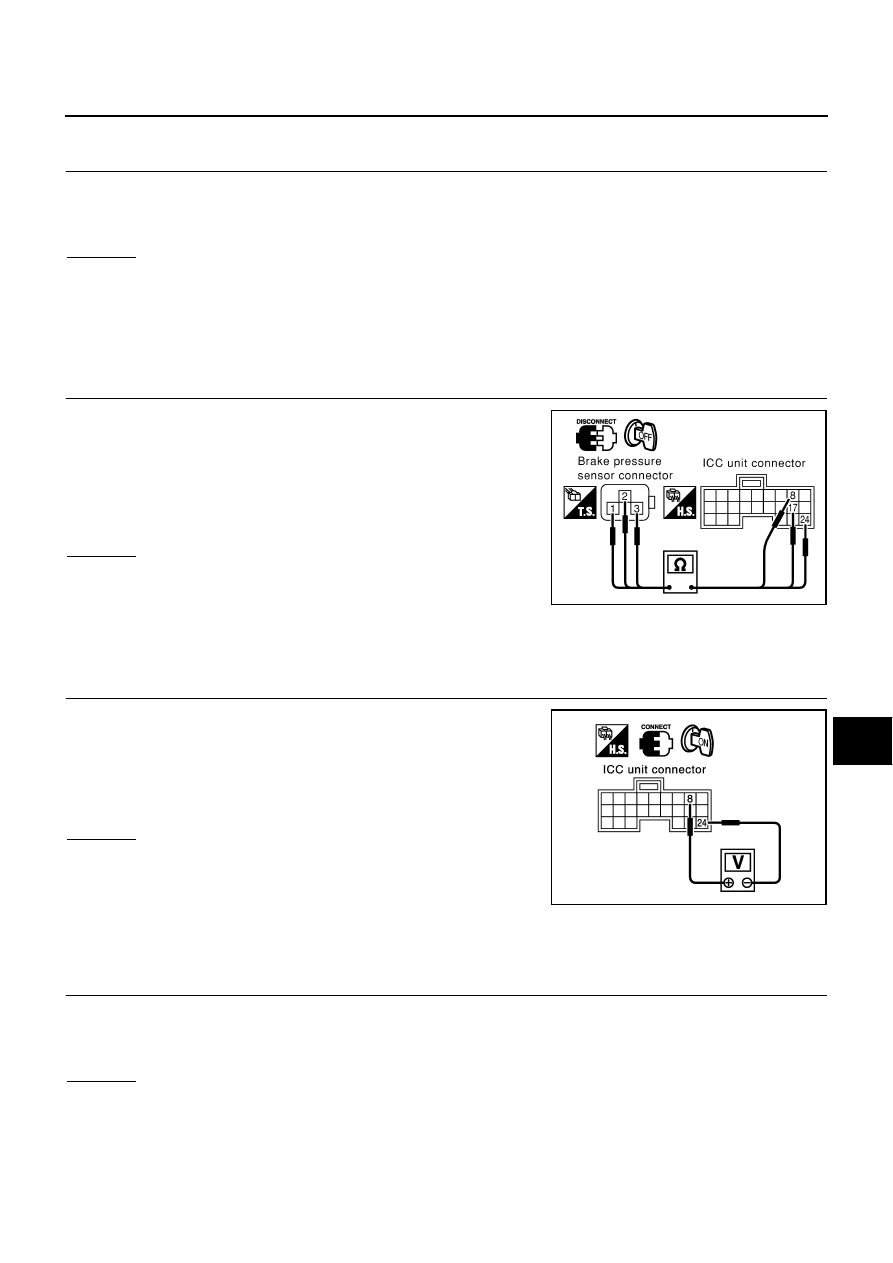
CHECK HARNESS BETWEEN BRAKE PRESSURE SENSOR AND ICC UNIT
1.
Turn ignition switch OFF.
2.
Disconnect connectors of ICC unit and brake pressure sensor.
3.
Check continuity between ICC unit harness connector B243 ter-
minal 8 (P/U), 17 (B/Y), 24 (OR) and brake pressure sensor har-
ness connector E82 terminal 3 (P/U), 2 (B/Y), 1 (OR).
OK or NG
NG
>>
●
Repair harness between brake pressure sensor and
ICC unit
●
After repair, erase DTC and perform ICC system run-
ning test. Then, perform self-diagnosis of ICC system again.
OK
>> GO TO 3.
3.
CHECK POWER SUPPLY CIRCUIT FOR BRAKE PRESSURE SENSOR
1.
Connect ICC unit.
2.
Turn ignition switch ON.
3.
Check voltage between ICC unit harness connector B243 termi-
nal 8 (P/U) and 24 (OR).
OK or NG
NG
>> Replace ICC unit. Clear DTC and perform driving check.
Then perform self-diagnosis of ICC system again.
OK
>>
●
Brake pressure sensor malfunction
●
Replace master cylinder assembly. Erase DTC and
perform ICC system running test. Then perform self-diagnosis of ICC system again.
DTC 62 BOOSTER SOL/V CIRCUIT
EKS003PJ
1.
CHECK SOLENOID/RELEASE SWITCH AND ICC UNIT CHECK CONNECTOR
1.
Turn ignition switch OFF.
2.
Disconnect connectors of brake booster solenoid/release and ICC unit, and connect them securely again.
Then erase DTC. After that perform self-diagnosis of ICC system again.
OK or NG
OK
>>
●
Poor connector connection
●
Check connector. (Check connector housing for disconnected, loose, bent, and collapsed ter-
minals. If any malfunction is detected, repair applicable part.) After repair, erase DTC, and per-
form ICC system running test. Then perform self-diagnosis of ICC system again.
NG
>> GO TO 2.
8 - 3, 17 - 2, 24 - 1
Continuity should exist.
SKIA1591E
8 (+) - 24 (–)
Approx. 5V
SKIA1268E