Infiniti I35 (A33). Manual - part 493
SEM947G
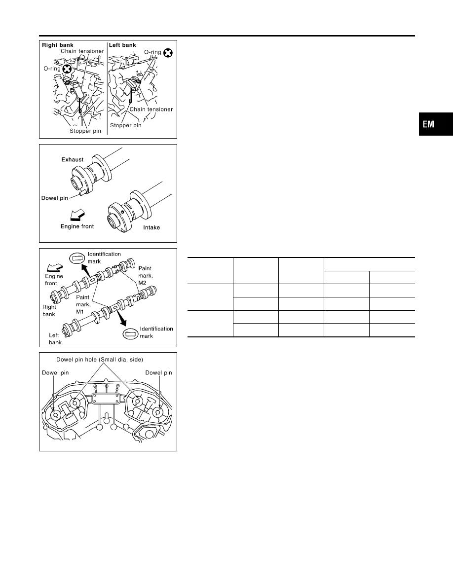
6.
Install camshaft chain tensioners on both sides of cylinder
head.
KBIA1071E
7.
Install exhaust and intake camshafts and camshaft brackets.
I
Exhaust camshaft has a dowel pin on camshaft sprocket
mounting flange. Install it on the exhaust side.
SEM653F
I
Identification marks are present on camshafts.
Bank
INT/EXH
ID mark
Paint mark
M1
M2
RH
INT
RE
Yes
No
EXH
RE
No
Yes
LH
INT
LH
Yes
No
EXH
LH
No
Yes
KBIA1072E
I
Position camshaft
RH exhaust camshaft dowel pin at about 10 o’clock
LH exhaust camshaft dowel pin at about 2 o’clock
GI
MA
LC
EC
FE
AT
AX
SU
BR
ST
RS
BT
HA
SC
EL
IDX
CYLINDER HEAD
Installation (Cont’d)
EM-63