Infiniti I35 (A33). Manual - part 419


  Index      Infiniti     Infiniti I35 (A33) - service repair manual 2004 year


Search            


Content   ..  417  418  419  420   ..


Infiniti I35 (A33). Manual - part 419


6

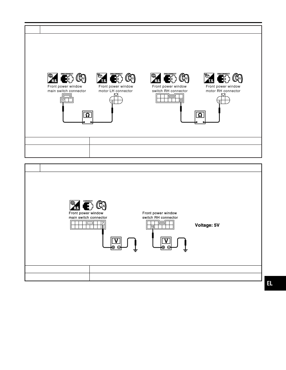
CHECK POWER WINDOW MOTOR GROUND CIRCUIT

1. Disconnect front power window main switch connector or front power window switch RH connector.
2. Check the following.

I

Continuity between front power window main switch harness connector D13 terminal 17 (W/B) and front power window
motor LH harness connector D4 terminal 6 (W/B).

I

Continuity between front power window switch RH harness connector D33 terminal 20 (W/B) and front power window
motor RH harness connector D38 terminal 6 (W/B).

SEL843YA

OK or NG

OK

©

Replace front power window motor LH or RH.

NG

©

Repair harness or connectors between power window switch and front power window
motor.

7

CHECK ENCODER POWER SUPPLY OUTPUT SIGNAL

1. Connect front power window main switch or front power window switch RH connector.
2. Turn ignition switch to ON position.
3. Check voltage between front power window main switch harness connector D10 terminal 7 (G/R) or front power win-

dow switch RH harness connector D33 terminal 15 (G/R) and ground.

SEL844Y

OK or NG

OK

©

GO TO 8.

NG

©

Replace front power window main switch or front power window switch RH.

GI

MA

EM

LC

EC

FE

AT

AX

SU

BR

ST

RS

BT

HA

SC

IDX

POWER WINDOW

Trouble Diagnoses (Cont’d)

EL-277

8

CHECK ENCODER POWER SUPPLY INPUT SIGNAL

Check voltage between front power window motor LH harness connector D4 terminal 4 (G/R) or front power window motor
RH harness connector D38 terminal 4 (G/R) and ground.

SEL838YA

OK or NG

OK

©

GO TO 9.

NG

©

Repair harness or connector.

9

CHECK ENCODER INPUT SIGNAL

1. Connect front power window motor LH or RH connector.
2. Check voltage signal between front power window main switch harness connector D10 terminal 14 (G/Y) or front power

window switch RH harness connector D33 terminal 19 (G/Y) and ground with oscilloscope when power window is in
automatic closing operation.

SEL727W

OK or NG

OK

©

Replace front power window main switch or front power window switch RH.

NG

©

GO TO 10.

POWER WINDOW

Trouble Diagnoses (Cont’d)

EL-278

10

CHECK HARNESS FOR OPEN OR SHORT

1. Turn ignition switch to OFF position.
2. Disconnect front power window main switch connector or front power window switch RH and front power window motor

LH or RH connector.

3. Check the following.

I

Check continuity between front power window main switch harness connector D10 terminal 14 (G/Y) and front power
window motor LH harness connector D4 terminal 5 (G/Y).

I

Check continuity between front power window switch RH harness connector D33 terminal 19 (G/Y) and front power win-
dow motor RH harness connector D38 terminal 5 (G/Y).

I

Check continuity between front power window main switch harness connector D10 terminal 14 (G/Y) or front power win-
dow switch RH harness connector D33 terminal 19 (G/Y) and ground.

SEL894YA

OK or NG

OK

©

Replace front power window motor LH or RH.

NG

©

Repair harness or connector.

GI

MA

EM

LC

EC

FE

AT

AX

SU

BR

ST

RS

BT

HA

SC

IDX

POWER WINDOW

Trouble Diagnoses (Cont’d)

EL-279

Component Parts and Harness Connector
Location

NHEL0106

SEL053YA

System Description

NHEL0107

OPERATION

NHEL0107S04

I

The lock/unlock switches (LH and RH) on door trim can lock and unlock all doors.

I

With the door key inserted in the key cylinder on front LH, turning it to “LOCK”, will lock all doors; turning
it to “UNLOCK” once unlocks the corresponding door; turning it to “UNLOCK” again within 5 seconds after
the first unlock operation unlocks all of the other doors. (Signals from door key cylinder switch)
Select unlock mode can be changed by CONSULT-II (EL-287).

I

If the ignition key is in the ignition key cylinder and one or more of the doors are open, setting the lock/
unlock switch to “LOCK” locks the doors once but then immediately unlocks them. Key reminder door mode
can be changed by CONSULT-II (EL-287).

POWER DOOR LOCK

Component Parts and Harness Connector Location

EL-280


Content   ..  417  418  419  420   ..