Infiniti I35 (A33). Manual - part 308
8
DETECT MALFUNCTIONING PART
Check the following.
I
EVAP canister for damage
I
EVAP hose between EVAP canister and water separator for clogging or poor connection
©
Repair hose or replace EVAP canister.
9
CHECK EVAP CONTROL SYSTEM PRESSURE SENSOR HOSE
Check disconnection or improper connection of hose connected to EVAP control system pressure sensor.
OK or NG
OK
©
GO TO 10.
NG
©
Repair it.
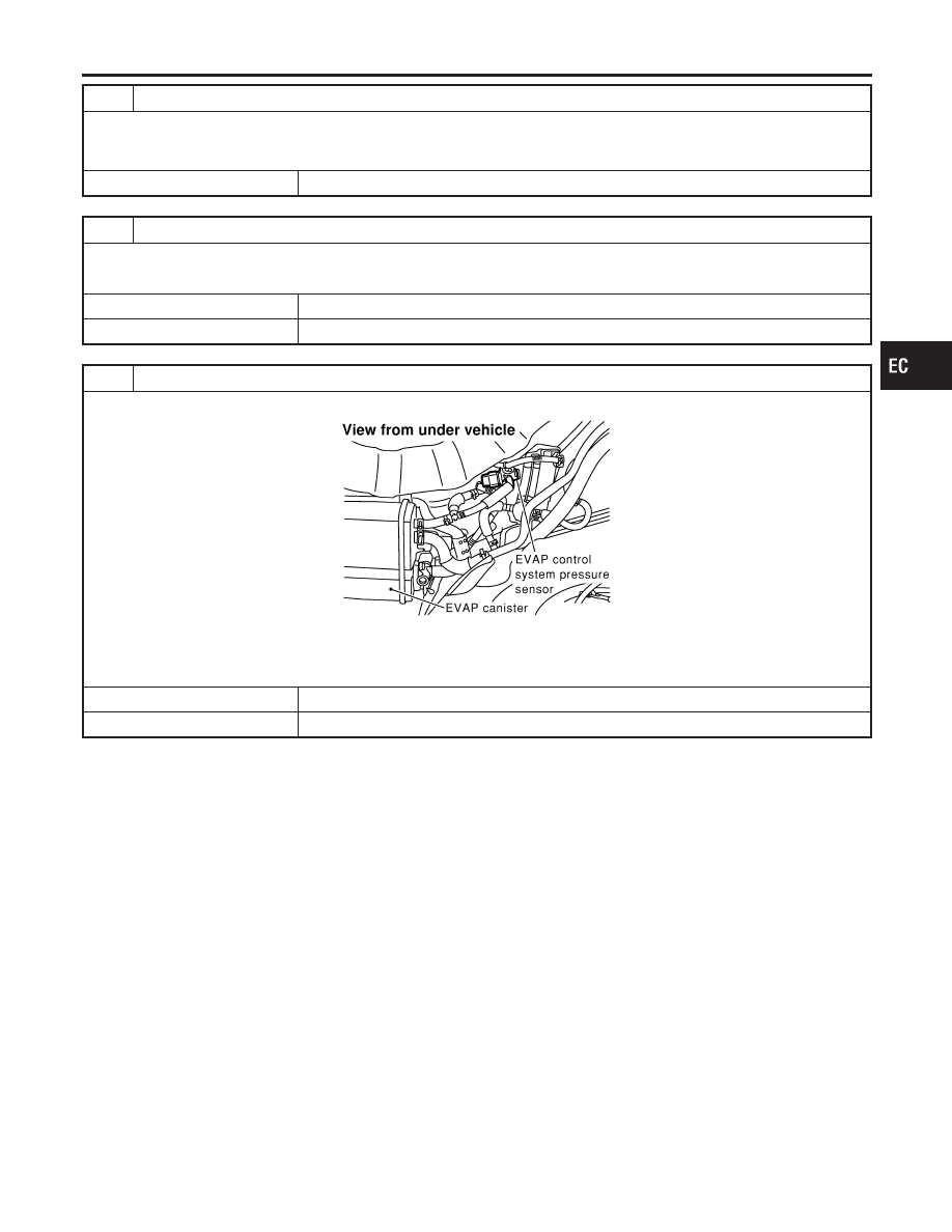
10
CHECK EVAP CONTROL SYSTEM PRESSURE SENSOR CONNECTOR
1. Disconnect EVAP control system pressure sensor harness connector.
SEF268X
2. Check connectors for water.
Water should not exist.
OK or NG
OK
©
GO TO 11.
NG
©
Replace EVAP control system pressure sensor.
GI
MA
EM
LC
FE
AT
AX
SU
BR
ST
RS
BT
HA
SC
EL
IDX
DTC P1448 EVAP CANISTER VENT CONTROL VALVE
Diagnostic Procedure (Cont’d)
EC-573