Infiniti G37 Coupe. Manual - part 928
MWI-58
< COMPONENT DIAGNOSIS >
METER CONTROL SWITCH SIGNAL CIRCUIT
Is the inspection result normal?
YES
>> INSPECTION END
NO
>> Repair harness or connector.
Component Inspection
INFOID:0000000001606680
1.
CHECK METER CONTROL SWITCH UNIT
1.
Turn the ignition switch OFF.
2.
Disconnect the meter control switch connector.
3.
Check continuity of the meter control switch.
Is the inspection result OK?
YES
>> INSPECTION END
NO
>> Replace the meter control switch.
Combination meter
Ground
Continuity
Connector
Terminals
M53
16
Not existed
36
37
39
40
38
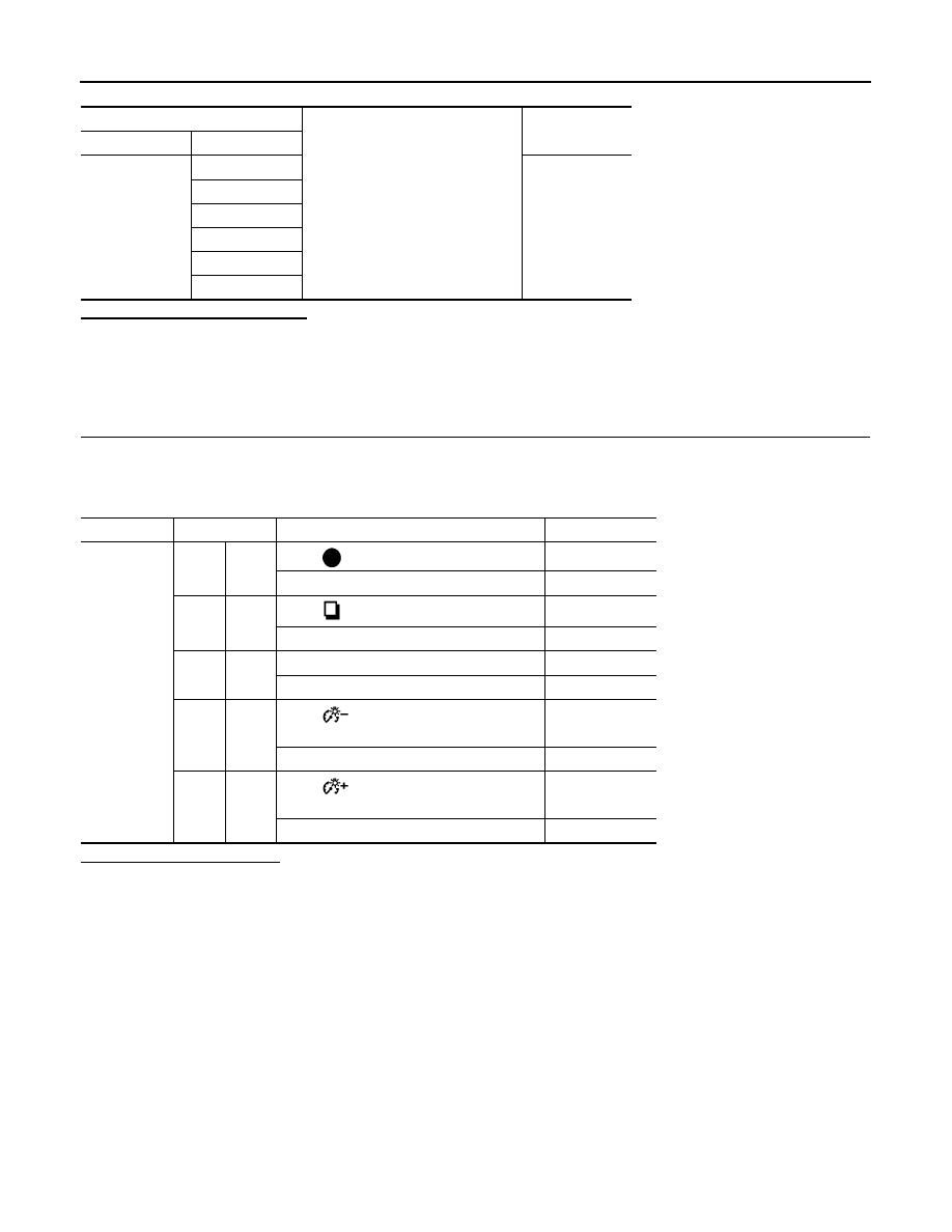
Connector
Terminal No.
Operation and status
Continuity
M54
2
7
When
(select) switch is pressed
Existed
Other than the above
Not existed
1
7
When
(enter) switch is pressed
Existed
Other than the above
Not existed
5
7
When trip A/B reset switch is pressed
Existed
Other than the above
Not existed
10
7
When
(illumination control) switch is
pressed
Existed
Other than the above
Not existed
9
7
When
(illumination control) switch is
pressed
Existed
Other than the above
Not existed