Infiniti G37 Coupe. Manual - part 913


  Index      Infiniti     Infiniti G37 Coupe - service repair manual 2008 year


Search            


Content   ..  911  912  913  914   ..


Infiniti G37 Coupe. Manual - part 913


DOOR MIRROR

MIR-71

< ON-VEHICLE REPAIR >

[WITHOUT ADP]

C

D

E

F

G

H

I

J

K

M

A

B

MIR

N

O

P

GLASS MIRROR : Disassembly and Assembly

INFOID:0000000001831200

DISASSEMBLY

1.

Remove the pawls and disassemble the base cover.

2.

Place the glass mirror upward.

3.

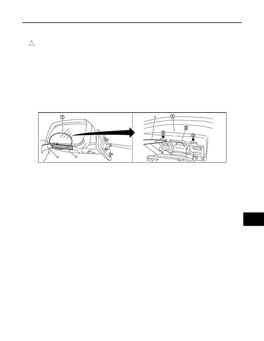
Put a strip of protective tape (B) on housing assembly.

4.

As shown in the figure, insert a small slotted screwdriver (A) into the recess between glass mirror (1) and
actuator (2). Push up two pawls (3) to remove glass mirror lower half side. 
NOTE:
• When pushing up pawls do not attempt to use one recess only. Be sure to push up with both recesses.
• Insert screwdriver into recesses, and push up while rotating (twisting) to make work easier.

5.

Remove two terminals of mirror heater attachment.

6.

Lightly lift up lower side of glass mirror, and detach two pawls of upper side as if pulling it out. Disassem-
ble glass mirror from actuator.
NOTE:
Be certain not to allow grease on sealing agent in center of mirror or back side of glass mirror.

ASSEMBLY

Assemble in the reverse order of disassemble.

CAUTION:

After installation, visually check that pawls are securely engaged.

DOOR MIRROR COVER

DOOR MIRROR COVER : Exploded View

INFOID:0000000001831203

DISASSEMBLY

1.

Mirror assembly

2.

Door mirror actuator

3.

Glass mirror

4.

Base cover

5.

Door mirror cover

: Pawl

JMLIA0056ZZ

MIR-72

< ON-VEHICLE REPAIR >

[WITHOUT ADP]

DOOR MIRROR

DOOR MIRROR COVER : Disassembly and Assembly

INFOID:0000000001831204

CAUTION:

Do not damage the mirror bodies.

DISASSEMBLY

1.

Remove the glass mirror. Refer to 

MIR-71, "GLASS MIRROR : Disassembly and Assembly"

.

2.

Remove the pawls, and disassemble the door mirror cover from the mirror assembly.

ASSEMBLY

Install in the reverse order of removal.

CAUTION:

After installation, visually check that pawls are securely engaged.

1.

Mirror assembly

2.

Door mirror actuator

3.

Glass mirror

4.

Base cover

5.

Door mirror cover

: Pawl

JMLIA0081ZZ

DOOR MIRROR REMOTE CONTROL SWITCH

MIR-73

< ON-VEHICLE REPAIR >

[WITHOUT ADP]

C

D

E

F

G

H

I

J

K

M

A

B

MIR

N

O

P

DOOR MIRROR REMOTE CONTROL SWITCH

Exploded View

INFOID:0000000001911610

Refer to 

INT-11, "Exploded View"

Removal and Installation

INFOID:0000000001911611

REMOVAL

1.

Remove the power window main switch finisher (2).
 Refer to 

PWC-92, "Removal and Installation"

2.

Remove door mirror remote control switch (1) from power win-
dow main switch finisher (2) using screwdriver (A).

INSTALLATION

Install in the reverse order of removal.

: Pawl

JMLIA0071ZZ

MWI

MWI-1

DRIVER INFORMATION & MULTIMEDIA

C

D

E

F

G

H

I

J

K

L

M

B

SECTION 

MWI

A

O

P

CONTENTS

METER, WARNING LAMP & INDICATOR

BASIC INSPECTION  ....................................

4

DIAGNOSIS AND REPAIR WORKFLOW  ..........

4

Work flow  ..................................................................

4

FUNCTION DIAGNOSIS ...............................

6

METER SYSTEM .................................................

6

METER SYSTEM  .........................................................

6

METER SYSTEM : System Diagram ........................

6

METER SYSTEM : System Description  ....................

6

METER SYSTEM : Component Parts Location  ......

10

METER SYSTEM : Component Description  ...........

10

SPEEDOMETER ........................................................

11

SPEEDOMETER : System Diagram  .......................

11

SPEEDOMETER : System Description ...................

11

SPEEDOMETER : Component Parts Location  .......

12

SPEEDOMETER : Component Description  ............

12

TACHOMETER ..........................................................

13

TACHOMETER : System Diagram  .........................

13

TACHOMETER : System Description  .....................

13

TACHOMETER : Component Parts Location  .........

14

TACHOMETER : Component Description  ..............

14

ENGINE COOLANT TEMPERATURE GAUGE  ........

15

ENGINE COOLANT TEMPERATURE GAUGE : 
System Diagram ......................................................

15

ENGINE COOLANT TEMPERATURE GAUGE : 
System Description  .................................................

15

ENGINE COOLANT TEMPERATURE GAUGE : 
Component Parts Location ......................................

16

ENGINE COOLANT TEMPERATURE GAUGE : 
Component Description ...........................................

16

FUEL GAUGE ............................................................

17

FUEL GAUGE : System Diagram  ...........................

17

FUEL GAUGE : System Description  .......................

17

FUEL GAUGE : Component Parts Location  ...........

18

FUEL GAUGE : Component Description  ................

18

ODO/TRIP METER .....................................................

19

ODO/TRIP METER : System Diagram  ....................

19

ODO/TRIP METER : System Description ................

19

ODO/TRIP METER : Component Parts Location ....

20

ODO/TRIP METER : Component Description  .........

20

SHIFT POSITION INDICATOR  ..................................

21

SHIFT POSITION INDICATOR : System Diagram ....

21

SHIFT POSITION INDICATOR : System Descrip-
tion ...........................................................................

21

SHIFT POSITION INDICATOR : Component 
Parts Location ..........................................................

22

SHIFT POSITION INDICATOR : Component De-
scription ...................................................................

22

WARNING LAMPS/INDICATOR LAMPS  ..................

23

WARNING LAMPS/INDICATOR LAMPS : System 
Diagram ...................................................................

23

WARNING LAMPS/INDICATOR LAMPS : System 
Description ...............................................................

23

WARNING LAMPS/INDICATOR LAMPS : Com-
ponent Parts Location ..............................................

24

WARNING LAMPS/INDICATOR LAMPS : Com-
ponent Description ...................................................

24

METER ILLUMINATION CONTROL  .........................

25

METER ILLUMINATION CONTROL : System Di-
agram ......................................................................

25

METER ILLUMINATION CONTROL : System De-
scription ...................................................................

25

METER ILLUMINATION CONTROL : Component 
Parts Location ..........................................................

26

METER ILLUMINATION CONTROL : Component 
Description ...............................................................

26

INFORMATION DISPLAY ..........................................

27

INFORMATION DISPLAY : System Diagram ..........

27

INFORMATION DISPLAY : System Description  .....

27

INFORMATION DISPLAY : Component Parts Lo-
cation .......................................................................

30

INFORMATION DISPLAY : Component Descrip-
tion ...........................................................................

30


Content   ..  911  912  913  914   ..