Infiniti G37 Coupe. Manual - part 620


  Index      Infiniti     Infiniti G37 Coupe - service repair manual 2008 year


Search            


Content   ..  618  619  620  621   ..


Infiniti G37 Coupe. Manual - part 620


TIMING CHAIN

EM-55

< ON-VEHICLE REPAIR >

C

D

E

F

G

H

I

J

K

L

M

A

EM

N

P

O

1.

Check that dowel pin (A) and crankshaft key (1) are located as
shown in the figure. (No. 1 cylinder at compression TDC)
NOTE:
Though camshaft does not stop at the position as shown in the
figure, for the placement of cam noses, it is generally accepted
that camshaft is placed in the same direction as that of the fig-
ure.

2.

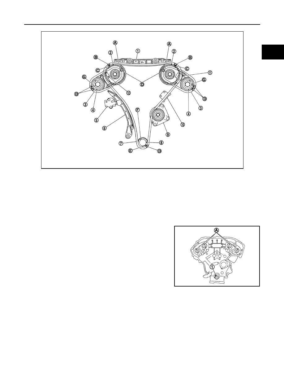
Install timing chains (secondary) and camshaft sprockets as follows:

CAUTION:

Matching marks between timing chain and sprockets slip easily. Confirm all matching mark posi-
tions repeatedly during the installation process.

1.

Internal chain guide

2.

Camshaft sprocket (INT)

3.

Timing chain (secondary)

4.

Camshaft sprocket (EXH)

5.

Timing chain tensioner (primary)

6.

Slack guide

7.

Timing chain (primary)

8.

Crankshaft sprocket

9.

Water pump

10. Tension guide

11.

Timing chain tensioner (secondary) 
(bank 2)

12.

Timing chain tensioner (secondary) 
(bank 1)

A.

Matching mark [punched (back side)]

B.

Matching mark (yellow link)

C.

Matching mark (punched)

D.

Matching mark (orange link)

E.

Matching mark (notched)

F.

Crankshaft key

G.

Matching mark [punched]

Camshaft dowel pin

: At cylinder head upper face side in each bank.

Crankshaft key

: At cylinder head side of bank 1.

JPBIA1107ZZ

JPBIA0094ZZ

EM-56

< ON-VEHICLE REPAIR >

TIMING CHAIN

a.

Push plunger of timing chain tensioner (secondary) and keep it
pressed in with a stopper pin (A).

b.

Install timing chains (secondary) and camshaft sprockets.
NOTE:
Figure shows bank 1 (rear view).

• Align the matching marks on timing chain (secondary) (orange

link) with the ones on intake and exhaust camshaft sprockets
(punched), and install them.
NOTE:
• Matching marks for camshaft sprockets (INT) are on the

back side of camshaft sprockets (secondary).

• There are two types of matching marks, the circle and oval

types. They should be used for the bank 1 and bank 2,
respectively.

• Align dowel pin camshafts with the pin groove on sprockets, and install them.
• In case that positions of each matching mark and each dowel pin do not fit with matching parts, make

fine adjustment to the position holding the hexagonal portion on camshaft (EXH) or drive shaft with
wrench or equivalent tool.

• Mounting bolts for camshaft sprockets must be tightened in the next step. Tightening them by hand is

sufficient to prevent the dislocation of dowel pins.

• It may be difficult to visually check the dislocation of matching

marks during and after installation. To make the matching eas-
ier, make a matching mark on the top of sprocket teeth and its
extended line in advance with paint.

c.

Tighten camshaft sprocket (EXH) mounting bolt.
• Secure camshaft (EXH) using a wrench at the hexagonal portion to tighten mounting bolt.

JPBIA0095ZZ

A

:  Camshaft  sprocket (INT) back face

B

: Orange link

C

: Dowel groove

D

: Matching mark (oval)

E

: Matching mark (2 oval: on front face)

F

: Matching mark (circle)

G

:  Camshaft  sprocket (EXH) back face

H

: Matching mark (2 circle: on front face)

I

: Timing chain (secondary)

Bank 1

: Use circle type

Bank 2

: Use oval type

A

: Matching mark (painted)

B

: Matching mark (orange link)

JPBIA1109ZZ

JPBIA1110ZZ

TIMING CHAIN

EM-57

< ON-VEHICLE REPAIR >

C

D

E

F

G

H

I

J

K

L

M

A

EM

N

P

O

d.

After confirming the matching marks are aligned, tighten camshaft sprocket (INT) mounting bolt.
• Secure the hexagonal portion (located in between journal No.

1 and journal No. 2) of drive shaft (A) using a wrench to tighten
mounting bolt.

CAUTION:

When holding the hexagonal part of drive shaft on the
intake side with a wrench, be careful not to allow the
wrench to cause interference with other parts.

e.

Pull stopper pins (C) out from timing chain tensioners (second-
ary) (1), (2).

3.

Install timing chain (primary) as follows:

a.

Install crankshaft sprocket (1).

• Check that the matching marks on crankshaft sprocket face

the front of the engine.

b.

Install timing chain (primary).

1

: Camshaft (EXH) (bank 2)

: Engine front

JPBIA1332ZZ

A

:  Bank  1

B

:  Bank  2

JPBIA1105ZZ

A

: Matching mark (front side)

: Engine front

JPBIA1108ZZ

EM-58

< ON-VEHICLE REPAIR >

TIMING CHAIN

• Install timing chain (primary) so that the matching mark

(punched) (B) on camshaft sprocket (INT) (1) is aligned with
the yellow link (A) on timing chain, while the matching mark
(notched) (C) on crankshaft sprocket (2) is aligned with the
orange link (D) one on timing chain, as shown in the figure.

• When it is difficult to align matching marks of timing chain (pri-

mary) with each sprocket, gradually turn drive shaft using
wrench on the hexagonal portion to align it with the matching
marks.

4.

Install internal chain guide (1), slack guide (2), and tension guide
(3).

CAUTION:

3

:  Water  pump

JPBIA1338ZZ

JPBIA1104ZZ


Content   ..  618  619  620  621   ..