Infiniti G37 Coupe. Manual - part 299


  Index      Infiniti     Infiniti G37 Coupe - service repair manual 2008 year


Search            


Content   ..  297  298  299  300   ..


Infiniti G37 Coupe. Manual - part 299


CCS

INSPECTION AND ADJUSTMENT

CCS-9

< BASIC INSPECTION >

[INTELLIGENT CRUISE CONTROL]

C

D

E

F

G

H

I

J

K

L

M

B

N

P

A

4.

Remove the thread suspended to the right side of ICC target board and suspend a thread with weight on
tip on the center of the ICC target board. Then mark the point of weight on the ground.

5.

Pivot the edge of the ICC target board 25

°

 (a) to either side.

NOTE:
Approx. 90 mm (3.54 in) (b) shift rates the 25

°

 (a) movement.

>> GO TO 4.

4.

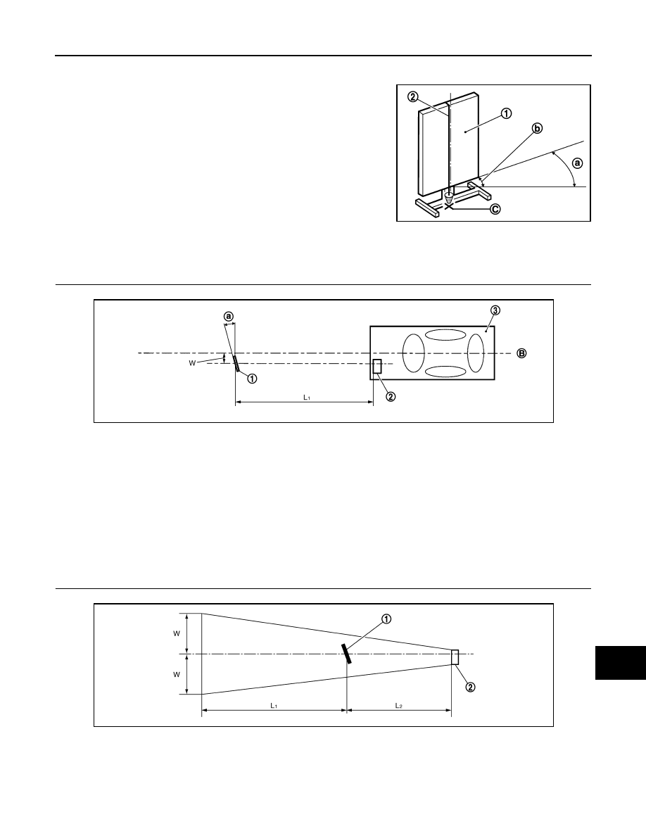
CHECKING THE ICC TARGET BOARD INSTALLATION POSITION

Check that the ICC target board (1) is located as shown in the figure. 

NOTE:
The distance between center of laser beam axis and ICC target board is 4 m (13.0 ft).

>> GO TO 5.

5.

CHECKING THE ICC TARGET BOARD INSTALLATION AREA

Do not place anything in the space shown in the figure (view from top).

NOTE:

1

: ICC target board

2

: String with a weight

C

: ICC target board center marking position

JSOIA0026ZZ

1.

ICC target board

2.

ICC sensor integrated unit

3.

Vehicle

B.

Vehicle center

L

1

.

4.0 m (13.0 ft)

W.

404 mm (15.91 in) (Leather grade type)

247 mm (9.72 in) (Sport grade type)

a.

25

°

JSOIA0017ZZ

1.

ICC target board

2.

ICC sensor integrated unit

L

1

.

6.5 m (21.3 ft)

L

2

.

4.0 m (13.0 ft)

W.

3.5 m (11.5 ft)

JSOIA0027ZZ

CCS-10

< BASIC INSPECTION >

[INTELLIGENT CRUISE CONTROL]

INSPECTION AND ADJUSTMENT

In case the space shown in the figure is not available, make a space by covering the side of the ICC target
board with a 1400 mm (4.6 ft)-size frosted black board or black cloth.

>> Go to 

CCS-10, "LASER BEAM AIMING ADJUSTMENT : Special Repair Requirement (Laser

Beam Aiming Adjustment)"

.

LASER BEAM AIMING ADJUSTMENT : Special Repair Requirement (Laser Beam 
Aiming Adjustment)

INFOID:0000000001606861

CAUTION:

Never view ICC sensor integrated unit body window directly during laser beam aiming adjustment.
NOTE:
Complete all necessary work for laser beam adjustment until the adjustment completes as shown in the proce-
dure. If the procedure does not complete, the ICC system is inoperable.

1.

SET CONSULT-III TO THE LASER BEAM AIMING ADJUSTMENT MODE

1.

Connect CONSULT-III and select “Work Support” of “ICC”. 

2.

Select “LASER BEAM ADJUST” after the “Work Support” screen is displayed. 

3.

Touch “START” after the “LASER BEAM ADJUST” screen is displayed.
NOTE:
If the adjustment screen does not appear on the CONSULT-III screen in 10 seconds. After touching
“LASER BEAM ADJUST” screen, the following causes may be considered:
• ICC target is not set accurately.
• There is not enough space beside the ICC target.
• The range of laser beam aiming exceeds for improper installation position.
- Deformation of vehicle body.
- Deformation of unit.
- Deformation of bracket.
• The area is not suitable for the adjustment work.
• ICC sensor integrated unit body window is not clean.
• The ICC system warning lamp illuminates.

>> GO TO 2.

2.

LASER BEAM AIMING ADJUSTMENT

1.

After the CONSULT-III displays “ADJUST THE VERTICAL OF LASER BEAM AIMING” turn the up-down
direction adjusting screw until “U/D CORRECT” value is set in the range of 

±

4.

NOTE:
• Turn the screw slowly. The value change on display is slower than actual movement of the ICC sensor

integrated unit. Wait for 2 seconds every time the screw is turned half a rotation.

• Turning the screw (A) clockwise to laser beam is downward

(B) and counterclockwise to laser beam is upward (C).

>> GO TO 3.

3.

LASER BEAM AIMING CONFIRMATION

1.

When “U/D CORRECT” value indicates 

±

4, confirm that the margin of value remains within 

±

4 at least for

2 seconds with no equipment or hand touching the ICC sensor integrated unit. 

2.

When “COMPLETED THE VERTICAL AIMING OF LASER BEAM” appears on screen, touch “END”.

JSOIA0018ZZ

CCS

INSPECTION AND ADJUSTMENT

CCS-11

< BASIC INSPECTION >

[INTELLIGENT CRUISE CONTROL]

C

D

E

F

G

H

I

J

K

L

M

B

N

P

A

NOTE:
Be sure that the margin of “U/D CORRECT” is within 

±

4 with ICC sensor integrated unit is untouched.

3.

Confirm that “ADJUSTING AUTOMATIC HORIZONTAL LASER BEAM AIMING” is on screen and wait for
a while (maximum: 10 seconds).

4.

Confirm that “NORMALLY COMPLETED” is displayed on CONSULT-III and close the aiming adjustment
procedure by touching “END”.
NOTE:
Complete all the procedures once “LASER BEAM ADJUST” mode is entered in CONSULT-III. When the
procedure is discontinued, the ICC system is inoperable.

>> LASER BEAM AIMING ADJUSTMENT END

ACTION TEST

ACTION TEST : Description

INFOID:0000000001606862

Always perform the ICC system action test to check that the ICC system operates normally after replacing the
ICC sensor integrated unit or repairing any ICC system malfunction. 

ACTION TEST : Special Repair Requirement (Vehicle-To-Vehicle Distance Control 
Mode)

INFOID:0000000001606863

NOTE:
• When there is no vehicle ahead, drive at the set speed steadily.
• When there is a vehicle ahead, control to maintain distance from the vehicle ahead, watching its speed.

1.

CHECK FOR MAIN SWITCH

1.

Start engine.

2.

Press the MAIN switch (1) for less than 1.5 seconds.

3.

Check the ICC system display in the combination meter to check
that the vehicle-to-vehicle distance control mode is ready for
activation. 

4.

Press the MAIN switch, and check that the ICC system display turns off when the ICC system is deacti-
vated. 

5.

Check that the ICC system display turns off after starting the engine again. 

>> GO TO 2.

2.

CHECK FOR DISTANCE SWITCH

1.

Start engine.

2.

Press the MAIN switch for less than 1.5 seconds.

3.

Press the DISTANCE switch.

ICC system display status

“CRUISE” indicator lamp (2)

:

ON

Set distance indicator (3)

:

Long mode

Own vehicle indicator (4)

:

ON

Set vehicle speed indicator (5)

:

“——”
“km/h (MPH)”

JSOIA0004ZZ

CCS-12

< BASIC INSPECTION >

[INTELLIGENT CRUISE CONTROL]

INSPECTION AND ADJUSTMENT

4.

Check if the set distance indicator changes display in order of: (Long)

(Middle)

(Short).

NOTE:
 The set distance indicator shows (Long) immediately after the engine starts.

>> GO TO 3.

3.

CHECK FOR RESUME/ACCELERATE, SET/COAST, CANCEL SWITCHES

1.

Check if RESUME/ACCELERATE, SET/COAST, CANCEL switches are operated smoothly.

2.

Check if switches come up as hand is released from the switches.

>> GO TO 4.

4.

SET CHECKING

1.

Start engine.

2.

Press the MAIN switch for less than 1.5 seconds.

3.

Drive the vehicle between 40 km/h (25 MPH) and 144 km/h (90 MPH).

4.

Push down the SET/COAST switch.

5.

Confirm that the desired speed is set as hand is released from the SET/COAST switch.

NOTE:
The set vehicle speed is displayed on the ICC system display.

>> GO TO 5.

5.

CHECK FOR INCREASE OF CRUISING SPEED

1.

Set vehicle-to-vehicle distance control mode at desired speed.

2.

Check if the set speed increases by 1 km/h (1 MPH) as RESUME/ACCELERATE switch is pushed up.

NOTE:
The maximum set speed of the vehicle-to-vehicle distance control mode is 144 km/h (90 MPH).

>> GO TO 6.

6.

CHECK FOR DECREASE OF CRUISING SPEED

1.

Set vehicle-to-vehicle distance control mode at desired speed.

2.

Check if the set speed decreases by 1 km/h (1 MPH) as SET/COAST switch is pushed down.

NOTE:
• Vehicle-to-vehicle distance control mode is automatically cancelled when the driving speed lowers to 32 km/

h (20 MPH) due to the deceleration of the vehicle ahead.

• The minimum set speed of the vehicle-to-vehicle distance control mode is 40 km/h (25 MPH).

>> GO TO 7.

JSOIA0005GB


Content   ..  297  298  299  300   ..