Infiniti G37 Coupe. Manual - part 246


  Index      Infiniti     Infiniti G37 Coupe - service repair manual 2008 year


Search            


Content   ..  244  245  246  247   ..


Infiniti G37 Coupe. Manual - part 246


BR-22

< ON-VEHICLE REPAIR >

BRAKE PIPING

4 PISTON TYPE

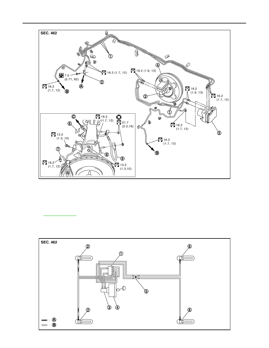
FRONT : Hydraulic Piping

INFOID:0000000001647840

1 PISTON TYPE

JPFIA0227GB

1.

Brake tube

2.

Connector

3.

Master cylinder

4.

Brake booster

5.

ABS actuator and electric unit (con-
trol unit)

6.

Lock plate

7.

Brake tube

8.

Brake hose bracket

9.

Brake hose

A.

To rear brake tube

B.

To front brake hose

C.

To front brake tube

Refer to 

GI-4, "Components"

 for symbols in the figure.

JPFIA0010ZZ

BRAKE PIPING

BR-23

< ON-VEHICLE REPAIR >

C

D

E

G

H

I

J

K

L

M

A

B

BR

N

O

P

4 PISTON TYPE

FRONT : Removal and Installation

INFOID:0000000001647841

REMOVAL

1 Piston Type

CAUTION:

Never spill or splash brake fluid on painted surfaces. Brake fluid may seriously damage paint. Wipe it
off immediately and wash with water if it gets on a painted surface.

1.

Remove tires with power tool.

2.

Drain brake fluid. Refer to 

BR-11, "Draining"

.

3.

Loosen the flare nut with a flare nut wrench and separate the brake tube from the hose.

CAUTION:

• Never scratch the flare nut and the brake tube.
• Never bend sharply, twist or strongly pull out the brake hoses and tubes.
• Cover open end of brake tubes and hoses when disconnecting to prevent entrance of dirt.

4.

Remove the union bolt and remove the brake hose from the brake caliper assembly.

5.

Remove the brake hose mounting nut.

6.

Remove the lock plate and remove the brake hose.

4 Piston Type

1.

ABS actuator and electric unit (con-
trol unit)

2.

Front disc brake

3.

Master cylinder

4.

Brake booster

5.

Connector

6.

Rear disc brake

A.

Brake hose

B.

Brake tube

 : Flare nut

 : Union bolt

 : Connector

JPFIA0211ZZ

1.

ABS actuator and electric unit (con-
trol unit)

2.

Front disc brake

3.

Master cylinder

4.

Brake booster

5.

Connector

6.

Rear disc brake

A.

Brake hose

B.

Brake tube

 : Flare nut

 : Union bolt

 : Connector

BR-24

< ON-VEHICLE REPAIR >

BRAKE PIPING

CAUTION:

Never spill or splash brake fluid on painted surfaces. Brake fluid may seriously damage paint. Wipe it
off immediately and wash with water if it gets on a painted surface.

1.

Remove tires with power tool.

2.

Drain brake fluid. Refer to 

BR-11, "Draining"

.

3.

Loosen the flare nut with a flare nut wrench and separate the brake tube from the brake hose and caliper.

CAUTION:

• Cover flare nut wrench with a cloth as not to damage the caliper.
• Never scratch the flare nut and the brake tube.
• Never bend sharply, twist or strongly pull out the brake hoses and tubes.
• Cover open end of brake tubes and hoses when disconnecting to prevent entrance of dirt.

4.

Remove the brake tube mounting bolt and remove the brake tube.

5.

Remove the brake hose mounting nut.

6.

Remove the lock plate and remove the brake hose.

INSTALLATION

1 Piston Type

CAUTION:

Never spill or splash brake fluid on painted surfaces. Brake fluid may seriously damage paint. Wipe it
off immediately and wash with water if it gets on a painted surface.
1.

Assemble the union bolt and the copper washer to the brake hose.

CAUTION:

Never reuse the copper washer.

2.

Align the brake hose pin to the projection (A) of the brake caliper
assembly and tighten the union bolt (1) to the specified torque.

3.

Install the brake tube to the brake hose, temporarily tighten the
flare nut by hand until it does not rotate further, and fix the brake
hose to the bracket with the lock plate.

CAUTION:

Check that all brake hoses and tubes are not twisted and
bent.

4.

Tighten the flare nut to the specified torque with a flare nut crow-
foot and a torque wrench.

CAUTION:

Never scratch the flare nut and the brake tube.

5.

Tighten the brake hose mounting nuts to the specified torque.

CAUTION:

Never reuse the brake hose mounting nuts.

6.

Refill with new brake fluid and perform the air bleeding. Refer to  

BR-12, "Bleeding Brake System"

.

CAUTION:

Never reuse drained brake fluid.

7.

Install tires.

4 Piston Type

CAUTION:

Never spill or splash brake fluid on painted surfaces. Brake fluid may seriously damage paint. Wipe it
off immediately and wash with water if it gets on a painted surface.

1.

Install the brake tube to the brake hose, temporarily tighten the flare nut by hand until it does not rotate
further, and fix the brake hose to the bracket with the lock plate.

CAUTION:

Check that all brake hoses and tubes are not twisted and bent.

2.

Tighten the brake hose mounting nuts to the specified torque.

CAUTION:

Never reuse the brake hose mounting nuts.

3.

Tighten the brake tube mounting bolt to the specified torque.

4.

Tighten the flare nut to the specified torque with a flare nut crowfoot and a torque wrench.

CAUTION:

JPFIA0011ZZ

BRAKE PIPING

BR-25

< ON-VEHICLE REPAIR >

C

D

E

G

H

I

J

K

L

M

A

B

BR

N

O

P

• Cover crowfoot with a cloth as not to damage the caliper.
• Never scratch the flare nut and the brake tube.

5.

Refill with new brake fluid and perform the air bleeding. Refer to  

BR-12, "Bleeding Brake System"

.

CAUTION:

Never reuse drained brake fluid.

6.

Install tires.

FRONT : Inspection

INFOID:0000000001647842

INSPECTION AFTER INSTALLATOIN

1.

Check the brake hoses and tubes for the following: no scratches; no twist and deformation; no interfer-
ence with other components when steering the steering wheel; no looseness at connections.

2.

Depress the brake pedal with a force of 785 N (80 kg, 176 lb) and hold down the pedal for approximately
5 seconds with the engine running. Check for any fluid leakage.

CAUTION:

Retighten the applicable connection to the specified torque and repair any abnormal (damaged,
worn or deformed) part if any brake fluid leakage is present.

REAR

REAR : Exploded View

INFOID:0000000001647843

1 PISTON TYPE

JPFIA0009GB

1.

Brake tube

2.

Brake hose

3.

Lock plate

4.

Union bolt

5.

Copper washer

A.

To front brake tube

B.

To rear brake hose

C.

To rear brake tube

Refer to 

GI-4, "Components"

 for symbols in the figure.


Content   ..  244  245  246  247   ..