Infiniti G37 Coupe. Manual - part 1453
WW-86
< ON-VEHICLE REPAIR >
FRONT WASHER NOZZLE AND TUBE
FRONT WASHER NOZZLE AND TUBE
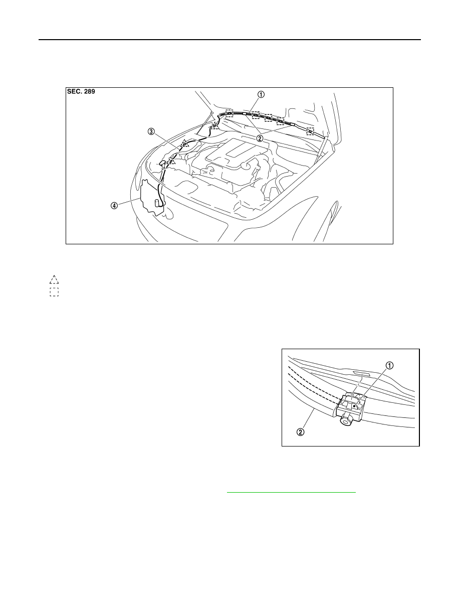
Hydraulic Layout
INFOID:0000000001629642
Removal and Installation
INFOID:0000000001629643
REMOVAL
1.
Open the hood.
2.
Use the stop point of washer nozzle (1) as the support point and
rotate nozzle to remove it from body, while pushing nozzle spray
point side along the hood.
3.
Remove the washer tube (2) from the washer nozzle.
INSTALLATION
1.
Install washer tube into the washer nozzle.
2.
Install the washer nozzle to the hood.
3.
Adjust the washer nozzle spray position. Refer to
WW-86, "Inspection and Adjustment"
CAUTION:
The spray positions differ. Check that left and right nozzles are installed correctly.
Inspection and Adjustment
INFOID:0000000001629644
INSPECTION
Washer Nozzle Inspection
1.
Washer tube
2.
Washer nozzle
3.
Washer tube
4.
Washer tank
: Clip
: Clip
JPLIA0560ZZ
JPLIA0561ZZ