Infiniti G37 Coupe. Manual - part 1356


  Index      Infiniti     Infiniti G37 Coupe - service repair manual 2008 year


Search            


Content   ..  1354  1355  1356  1357   ..


Infiniti G37 Coupe. Manual - part 1356


TRANSMISSION ASSEMBLY

TM-277

< DISASSEMBLY AND ASSEMBLY >

[5AT: RE5R05A]

C

E

F

G

H

I

J

K

L

M

A

B

TM

N

O

P

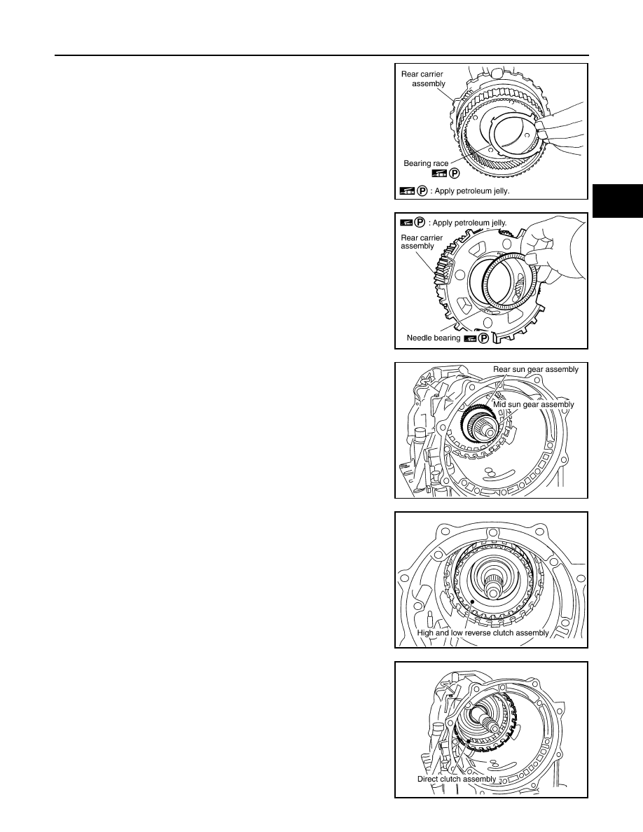
20. Remove bearing race from rear carrier assembly.

21. Remove needle bearing from rear carrier assembly.

22. Remove mid sun gear assembly, rear sun gear assembly and

high and low reverse clutch hub as a unit.

CAUTION:

Be careful to remove then with bearing race and needle
bearing.

23. Remove high and low reverse clutch assembly from direct clutch

assembly.

CAUTION:

Make sure that needle bearing is installed to the high and
low reverse clutch assembly edge surface.

24. Remove direct clutch assembly from reverse brake.

SCIA5175E

SCIA2803E

SCIA5018E

SCIA2306E

SCIA5019E

TM-278

< DISASSEMBLY AND ASSEMBLY >

[5AT: RE5R05A]

TRANSMISSION ASSEMBLY

25. Remove needle bearing from drum support.

26. Remove snap ring (1) from A/T assembly harness connector

(A).

27. Push A/T assembly harness connector (A).

CAUTION:

Be careful not to damage connector.

28. Remove clips (1).

29. Remove oil pan (2) and oil pan gasket.

30. Remove magnets (1) from oil pan.

SCIA5198E

JPDIA0007ZZ

JPDIA0008ZZ

3

: Drain plug

: Front

: Oil pan mounting bolt

SCIA8117E

JPDIA0009ZZ

TRANSMISSION ASSEMBLY

TM-279

< DISASSEMBLY AND ASSEMBLY >

[5AT: RE5R05A]

C

E

F

G

H

I

J

K

L

M

A

B

TM

N

O

P

31. Disconnect A/T fluid temperature sensor 2 connector (A).

CAUTION:

Be careful not to damage connector.

32. Disengage terminal clips (

).

33. Disconnect revolution sensor connector (A).

CAUTION:

Be careful not to damage connector.

34. Disengage terminal clip (

).

35. Remove bolts A, B and C from control valve with TCM.

36. Remove control valve with TCM from transmission case.

CAUTION:

When removing, be careful with the manual valve notch and
manual plate height. Remove it vertically.

37. Remove A/T fluid temperature sensor 2 (1) with bracket (2) from

control valve with TCM.

SCIA8124E

JPDIA0011ZZ

: Front

Bolt symbol

Length mm (in)

Number of bolts

A

42 (1.65)

5

B

55 (2.17)

6

C

40 (1.57)

1

SCIA8077E

SCIA5260E

: Bolt

JPDIA0013ZZ

TM-280

< DISASSEMBLY AND ASSEMBLY >

[5AT: RE5R05A]

TRANSMISSION ASSEMBLY

38. Remove bracket (1) from A/T fluid temperature sensor 2 (2).

39. Remove O-ring (1) from A/T assembly harness connector (A).

40. Disconnect TCM connectors (A) and (B).

CAUTION:

Be careful not to damage connectors.

41. Remove A/T assembly harness connector (A) from control valve

with TCM using a flat-bladed screwdriver (B).

42. Disconnect TCM connector (A) and park/neutral position switch

connector (B).

CAUTION:

Be careful not to damage connectors.

JPDIA0014ZZ

JPDIA0015ZZ

JPDIA0016ZZ

JPDIA0017ZZ

JPDIA0018ZZ


Content   ..  1354  1355  1356  1357   ..