Infiniti G37 Coupe. Manual - part 1302


  Index      Infiniti     Infiniti G37 Coupe - service repair manual 2008 year


Search            


Content   ..  1300  1301  1302  1303   ..


Infiniti G37 Coupe. Manual - part 1302


MAINSHAFT AND GEAR

TM-61

< DISASSEMBLY AND ASSEMBLY >

[6MT: FS6R31A]

C

E

F

G

H

I

J

K

L

M

A

B

TM

N

O

P

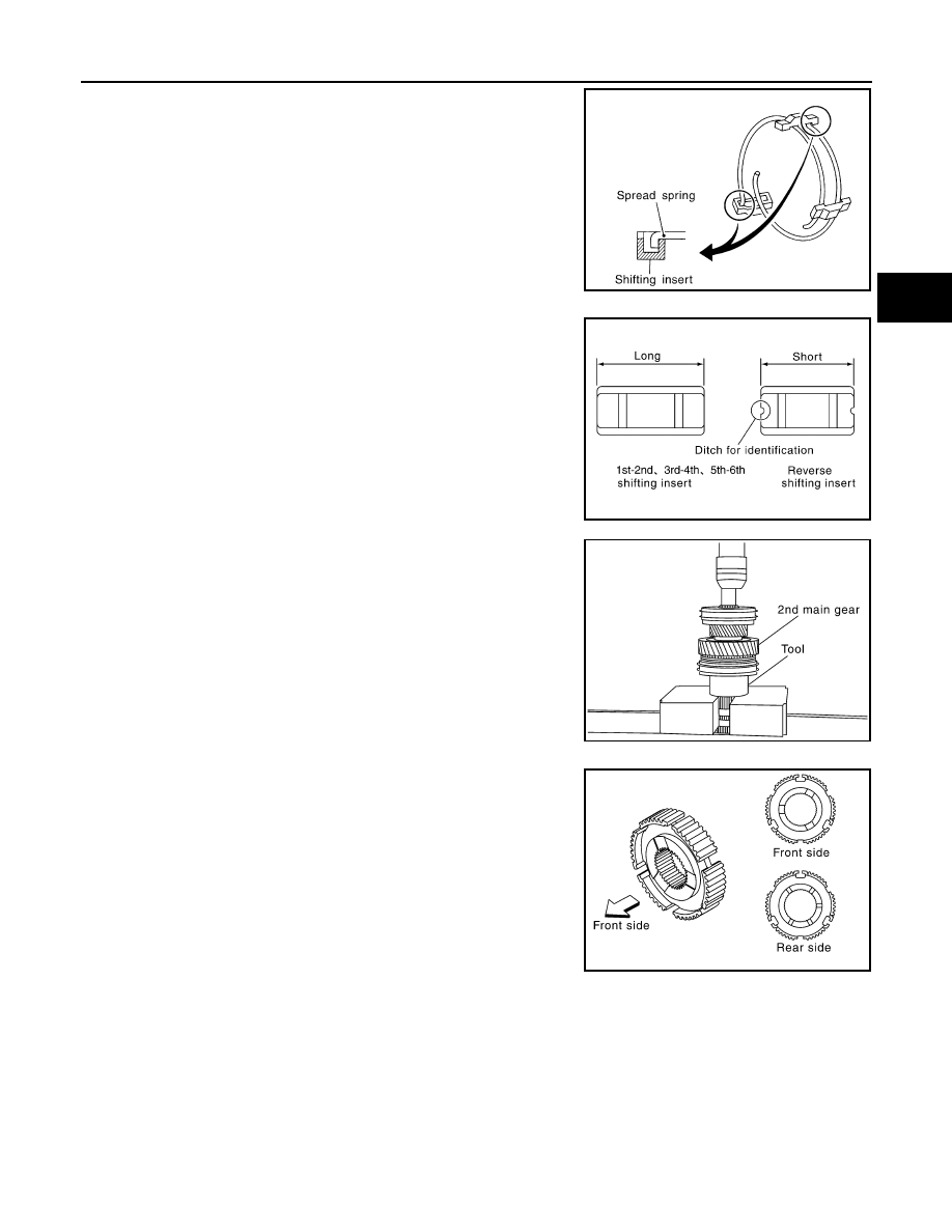
• Never install 1st-2nd spread spring hook onto the same

1st-2nd shifting insert.

• Be careful with the shape of reverse shifting insert to

avoid misassembly.

8.

Apply recommended grease to 2nd needle bearing.

9.

Install 2nd main gear, 2nd needle bearing, 2nd inner baulk ring,
2nd synchronizer cone and 2nd outer baulk ring on mainshaft
and then using a support ring [SST: ST27861000 (

)] and

a press to press fit 1st-2nd synchronizer assembly.

CAUTION:

• Replace 2nd inner baulk ring, 2nd synchronizer cone and

2nd outer baulk ring as a set.

• When press fitting, install with the side having the three

boss edge oil grooves facing the front side.

NOTE:

SCIA1600E

PCIB0608E

PCIB0202E

PCIB1364E

TM-62

< DISASSEMBLY AND ASSEMBLY >

[6MT: FS6R31A]

MAINSHAFT AND GEAR

1st baulk ring has three spaces that four gear tooth is missing
and 2nd baulk ring has three spaces that two gear teeth are
missing.

10. Using a support ring [SST: ST27861000 (

)] and a press to

press fit 1st gear bushing.

11. Apply recommended grease to 1st needle bearing.

12. Install 1st outer baulk ring, 1st synchronizer cone, 1st inner

baulk ring, 1st needle bearing and 1st main gear on mainshaft
and then using the inserter [SST: ST30022000 (

)] and a

press to press fit 3rd main gear.

CAUTION:

• Never reuse 3rd main gear.
• Replace 1st outer baulk ring, 1st synchronizer cone and

1st inner baulk ring as a set.

13. Install 3rd-4th main spacer on mainshaft and then using the

inserter [SST: ST30022000 (

)] and a press to press fit 4th

main gear.

CAUTION:

• Never reuse 4th main gear.
• When installing, set boss to rear side.

14. Using the inserter and a press to press fit mainshaft bearing

onto mainshaft.

PCIB1314E

PCIB0203E

PCIB0745E

PCIB0612E

PCIB1257E

MAINSHAFT AND GEAR

TM-63

< DISASSEMBLY AND ASSEMBLY >

[6MT: FS6R31A]

C

E

F

G

H

I

J

K

L

M

A

B

TM

N

O

P

15. Using the inserter [SST: ST30911000 (

)] and a press to

press fit reverse main gear bushing onto mainshaft.

Inspection

INFOID:0000000001732889

MAINSHAFT AND GEAR

If the contact surface on each gear and mainshaft, etc. has damage,
peeling, abrasion, dent, bent, or any other damage, replace the com-
ponents.

SYNCHRONIZER

Synchronizer Hub and Coupling Sleeve

• If the contact surface on coupling sleeve, synchronizer hub and

shifting insert has damage or abrasion, replace the components.

• Coupling sleeve and synchronizer hub shall move smoothly.

Baulk Ring and Spread Spring

• If the cam surface on baulk ring or contact surface on insert has

damage or excessive wear, replace with a new one.

• If spread spring is damaged, replace with a new one.

Baulk Ring Clearance for Single Cone Synchronizer (6th and Reverse)

PCIB0206E

SCIA1680E

SMT387A

SCIA0608J

TM-64

< DISASSEMBLY AND ASSEMBLY >

[6MT: FS6R31A]

MAINSHAFT AND GEAR

• Push baulk ring on the cone and measure the clearance between

baulk ring and cone. If the measurement is below limit, replace it
with a new one.

Baulk Ring Clearance for Triple Cone Synchronizer (1st and 2nd)

• Check the clearance between outer baulk ring (1), synchronizer

cone (2), and inner baulk ring (3) as follows.

CAUTION:

The clearances “A”, “B” and “C” are controlled with outer
baulk ring, synchronizer cone, and inner baulk ring as a set.
Replace them as a set if the clearances are outside the limit
value.

1.

Measure the clearance “A” at 2 points or more diagonally oppo-
site using a feeler gauge (B) when pressing outer baulk ring (1),
synchronizer cone (2), and inner baulk ring (3) toward gear taper
cone (C). And then calculate mean value.

2.

Measure the clearance “B” at 2 points or more diagonally oppo-
site using a feeler gauge (A). And then calculate mean value.

Clearance

Standard value

: Refer to 

TM-75, "Baulk Ring Clear-

ance"

.

Limit value

: Refer to 

TM-75, "Baulk Ring Clear-

ance"

.

PCIB1328E

JPDIC0308ZZ

Clearance “A”

Standard value

: Refer to 

TM-75, "Baulk Ring Clear-

ance"

.

Limit value

Refer to 

TM-75, "Baulk Ring Clear-

ance"

.

JPDIC0034ZZ

1

: Outer baulk ring

2

: Synchronizer cone

Clearance “B”

Standard value

: Refer to 

TM-75, "Baulk Ring Clear-

ance"

.

Limit value

: Refer to 

TM-75, "Baulk Ring Clear-

ance"

.

JPDIC0307ZZ


Content   ..  1300  1301  1302  1303   ..