Content .. 1239 1240 1241 1242 ..
Infiniti G37 Coupe. Manual - part 1241
VEHICLE SPEED SIGNAL CIRCUIT
STC-15
< COMPONENT DIAGNOSIS >
[WITHOUT 4WAS]
C
D
E
F
H
I
J
K
L
M
A
B
STC
N
O
P
VEHICLE SPEED SIGNAL CIRCUIT
Description
INFOID:0000000001666278
• Unified meter and A/C amp. sends vehicle speed signal to power steering control unit.
Diagnosis Procedure
INFOID:0000000001666279
1.
PERFORM UNIFIED METER AND A/C AMP. SELF-DIAGNOSIS
With CONSULT-III
Perform unified meter and A/C amp. self-diagnosis.
Is any error system detected?
YES
>> Check the error system.
NO
>> GO TO 2.
2.
CHECK HARNESS BETWEEN UNIFIED METER AND A/C AMP. AND POWER STEERING CONTROL
UNIT
1.
Turn the ignition switch OFF.
2.
Disconnect unified meter and A/C amp. harness connector.
3.
Disconnect power steering control unit harness connector.
4.
Check continuity between unified meter and A/C amp. harness connector and power steering control unit
harness connector.
Also check harness for short to ground and short to power.
Is the inspection result normal?
YES
>> GO TO 3.
NO
>> Repair or replace damaged parts.
3.
CHECK VEHICLE SPEED SIGNAL (1)
1.
Turn the ignition switch OFF.
2.
Connect unified meter and A/C amp. harness connector.
3.
Check unified meter and A/C amp. input/output standard values. Refer to
Is the inspection result normal?
YES
>> GO TO 4.
NO
>> Replace unified meter and A/C amp. Refer to
4.
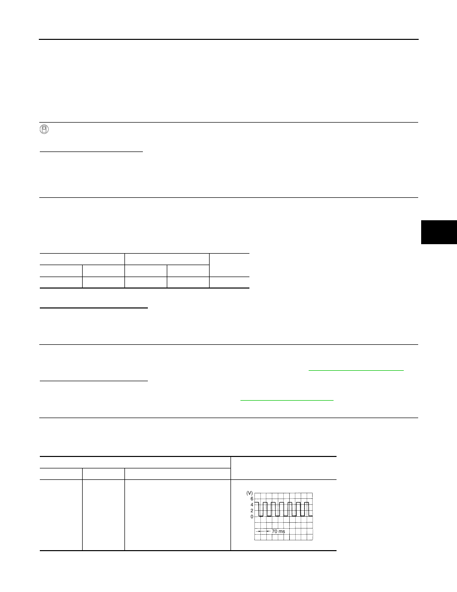
CHECK VEHICLE SPEED SIGNAL (2)
1.
Turn the ignition switch OFF.
2.
Connect power steering control unit harness connector.
3.
Check signal between power steering control unit harness connector and ground with oscilloscope.
Also check harness for short to ground and short to power.
Unified meter and A/C amp.
Power steering control unit
Continuity
Connector
Terminal
Connector
Terminal
M66
8
M108
8
Existed
Power steering control unit
Value (Approx.)
Connector
Terminal
Condition
M108
8 – Ground
Vehicle speed:
40 km/h (25 MPH)
CAUTION:
Check air pressure of tire under
standard condition.
SEIA0775E