Content .. 1006 1007 1008 1009 ..
Infiniti G37 Coupe. Manual - part 1008
PG
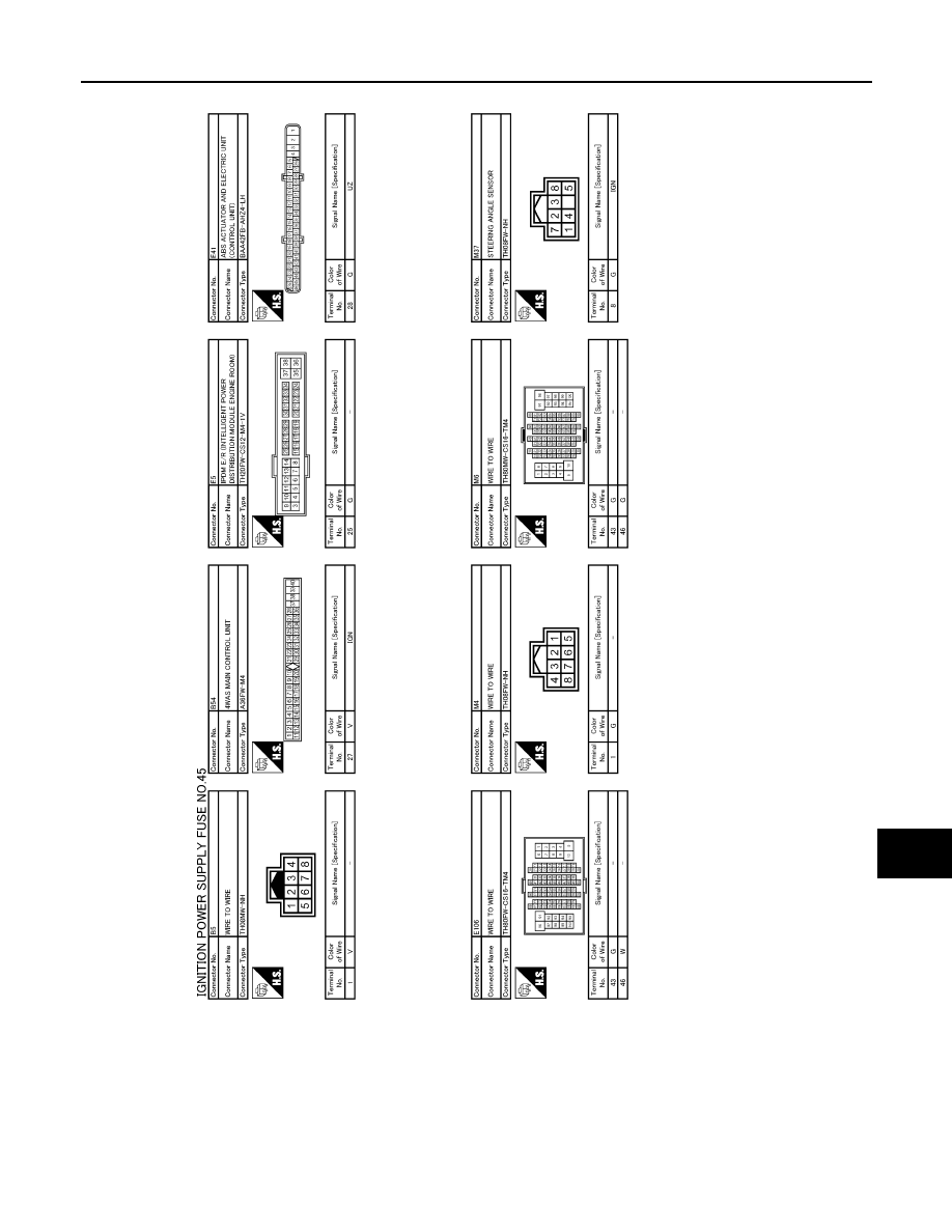
POWER SUPPLY ROUTING CIRCUIT
PG-71
< COMPONENT DIAGNOSIS >
[POWER SUPPLY&GROUND CIRCUIT]
C
D
E
F
G
H
I
J
K
L
B
A
O
P
N
JCMWA0922GB
|
|
|
Content .. 1006 1007 1008 1009 ..
PG POWER SUPPLY ROUTING CIRCUIT PG-71 < COMPONENT DIAGNOSIS > [POWER SUPPLY&GROUND CIRCUIT] C D E F G H I J K L B A O P N JCMWA0922GB |