Infiniti G37 Coupe. Manual - part 70


  Index      Infiniti     Infiniti G37 Coupe - service repair manual 2008 year


Search            


Content   ..  68  69  70  71   ..


Infiniti G37 Coupe. Manual - part 70


AV

U1216 AV CONTROL UNIT

AV-33

< COMPONENT DIAGNOSIS >

[BASE AUDIO WITHOUT NAVIGATION]

C

D

E

F

G

H

I

J

K

L

M

B

A

O

P

U1216 AV CONTROL UNIT

Description

INFOID:0000000001684429

Replace the AV control unit if this DTC is displayed. Refer to 

AV-109, "Exploded View"

.

DTC Logic

INFOID:0000000001684430
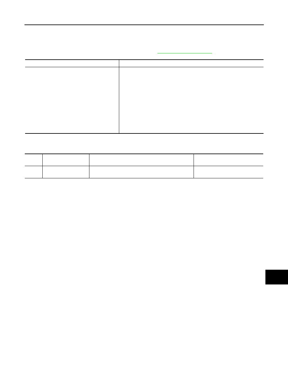
Part name

Description

AV CONTROL UNIT

• It is the master unit of the MULTI AV system, and it is connected to each control 

unit by communication. It operates each system according to communication 
signals from the AV control unit.

• AV control unit includes audio function and vehicle information function.
• It is connected to ECM and unified meter and A/C amp via CAN communica-

tion to obtain necessary information for the vehicle information function.

• It is connected to BCM via CAN communication transmitting/receiving for the 

vehicle settings function.

• It inputs the illumination signals that are required for the display dimming con-

trol.

• It inputs the signals for driving status recognition (vehicle speed, reverse and 

parking brake). 

• Auxiliary image signal is input from the auxiliary input jacks.

DTC

Display contents of 

CONSULT-III

DTC Detection Condition

Action to take

U1216

CAN CONT
[U1216]

Internal malfunction of AV control unit (CAN controller) is 
detected.

Replace AV control unit.

AV-34

< COMPONENT DIAGNOSIS >

[BASE AUDIO WITHOUT NAVIGATION]

U1243 DISPLAY UNIT

U1243 DISPLAY UNIT

Description

INFOID:0000000001689654

DTC Logic

INFOID:0000000001689655

Diagnosis Procedure

INFOID:0000000001689656

1.

CHECK DISPLAY UNIT POWER SUPPLY AND GROUND CIRCUIT

Check display unit power supply and ground circuit. Refer to 

AV-39, "DISPLAY UNIT : Diagnosis Procedure"

.

Is the inspection result normal?

YES

>> GO TO 2.

NO

>> Repair malfunctioning parts.

2.

CHECK CONTINUITY COMMUNICATION CIRCUIT

1.

Turn ignition switch OFF.

2.

Disconnect display unit connector and AV control unit connector.

3.

Check continuity between display unit harness connector terminals 11, 22 and AV control unit harness
connector terminals 56, 44.

4.

Check continuity between display unit harness connector terminals 11, 22 and ground.

Is the inspection result normal?

YES

>> GO TO 3.

NO

>> Repair harness or connector.

3.

CHECK COMMUNICATION SIGNAL

1.

Connect display unit connector and AV control unit connector.

2.

Turn ignition switch ON.

3.

Check signal between display unit harness connector terminal 11 and ground.

Part name

Description

DISPLAY UNIT

• Display image is controlled by the serial communication from AV control unit.
• Inputs the RGB image signal (RGB, RGB area and RGB synchronizing) from 

AV control unit and the auxiliary image signal from the auxiliary input jacks.

• Outputs the synchronizing signals (HP and VP) to the AV control unit.

DTC

Display contents of 

CONSULT-III

DTC Detection Condition

Possible causes

U1243

FRONT DISP CONN
[U1243]

• Display unit power supply and ground circuit malfunc-

tion is detected.

• Malfunction is detected in communication circuit be-

tween AV control unit and display unit.

• Malfunction is detected in communication signal be-

tween AV control unit and display unit.

• Display unit power supply and 

ground circuit.

• Communication circuit between AV 

control unit and display unit.

11 - 56

: Continuity should exist.

22 - 44

: Continuity should exist.

11, 22 - Ground

: Continuity should not exist.

AV

U1243 DISPLAY UNIT

AV-35

< COMPONENT DIAGNOSIS >

[BASE AUDIO WITHOUT NAVIGATION]

C

D

E

F

G

H

I

J

K

L

M

B

A

O

P

Is the inspection result normal?

YES

>> GO TO 4.

NO

>> Replace AV control unit.

4.

CHECK COMMUNICATION SIGNAL

Check signal between display unit harness connector terminal 22 and ground.

Is the inspection result normal?

YES

>> INSPECTION END

NO

>> Replace display unit.

Terminal

Condition

Reference value

11 - Ground

Ignition 

switch 

ON

When adjusting display bright-
ness.

PKIB5039J

Terminal

Condition

Reference value

22 - Ground

Ignition 

switch 

ON

When adjusting display bright-
ness.

PKIB5039J

AV-36

< COMPONENT DIAGNOSIS >

[BASE AUDIO WITHOUT NAVIGATION]

U1255 SATELLITE RADIO TUNER

U1255 SATELLITE RADIO TUNER

Description

INFOID:0000000001689657

DTC Logic

INFOID:0000000001689658

Diagnosis Procedure

INFOID:0000000001689659

1.

CHECK SATELLITE RADIO TUNER POWER SUPPLY AND GROUND CIRCUIT

Check satellite radio tuner power supply and ground circuit. Refer to 

AV-41, "SATELLITE RADIO TUNER :

Diagnosis Procedure"

.

Is the inspection result normal?

YES

>> GO TO 2.

NO

>> Repair malfunctioning parts.

2.

CHECK CONTINUITY COMMUNICATION CIRCUIT AND REQUEST SIGNAL CIRCUIT

1.

Turn ignition switch OFF.

2.

Disconnect AV control unit connector and satellite radio tuner connector.

3.

Check continuity between AV control unit harness connector terminals 28, 29, 30 and satellite radio tuner
harness connector terminals 8, 9, 10.

4.

Check continuity between AV control unit harness connector terminals 28, 29 and 30.

Is the inspection result normal?

YES

>> GO TO 3.

NO

>> Repair harness or connector.

3.

CHECK AV CONTROL UNIT VOLTAGE

1.

Connect AV control unit connector.

2.

Turn ignition switch ON.

3.

Check voltage between AV control unit harness connector terminal 28, 29 and ground.

Part name

Description

SATELLITE RADIO TUNER

• Inputs the satellite radio signal from satellite radio antenna and outputs it to the 

AV control unit.

• It is controlled with the communication (communication signal, request signal) 

from AV control unit.

DTC

Display contents of 

CONSULT-III

DTC Detection Condition

Possible causes

U1255

SAT CONN
[U1255]

• Satellite radio tuner power supply and ground circuit 

malfunction is detected.

• Malfunction is detected in communication circuit be-

tween AV control unit and satellite radio tuner.

• Malfunction is detected in communication signal be-

tween AV control unit and satellite radio tuner.

• Malfunction is detected in request signal circuit be-

tween AV control unit and satellite radio tuner.

• Satellite radio tuner power supply 

and ground circuit.

• Communication circuit between AV 

control unit and satellite radio tun-
er.

• Request signal circuit between AV 

control unit and satellite radio tun-
er.

28 - 8

: Continuity should exist.

29 - 9

: Continuity should exist.

30 - 10

: Continuity should exist.

28 - Ground

: Continuity should not exist.

29 - Ground

: Continuity should not exist.

30 - Ground

: Continuity should not exist.


Content   ..  68  69  70  71   ..