Infiniti G35 (V35) Sedan. Manual - part 750


  Index      Infiniti     Infiniti G35 (V35) Sedan - service repair manual 2007 year


Search            


Content   ..  748  749  750  751   ..


Infiniti G35 (V35) Sedan. Manual - part 750


HA-34

< ON-VEHICLE MAINTENANCE >

REFRIGERATION SYSTEM

Testing must be performed as follows:
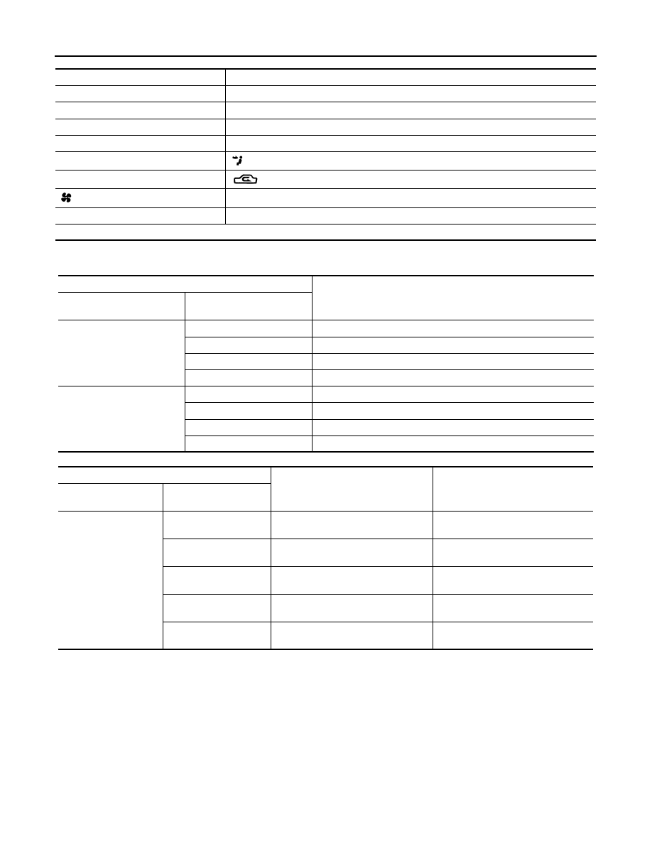
TEST READING

Recirculating-to-discharge Air Temperature Table

Ambient Air Temperature-to-operating Pressure Table

Refrigerant Leaks

INFOID:0000000000959864

Perform a visual inspection of all refrigeration parts, fittings, hoses and components for signs of A/C lubricant
leakage, damage and corrosion. A/C lubricant leakage may indicate an area of refrigerant leakage. Allow
extra inspection time in these areas when using either an electrical leak detector or fluorescent dye leak
detector (SST: J-42220).
If dye is observed, confirm the leak with an electrical leak detector. It is possible a prior leak was repaired and
not properly cleaned.
When searching for leaks, do not stop when one leak is found but continue to check for additional leaks at all
system components and connections.
When searching for refrigerant leaks using an electrical leak detector, move the probe along the suspected
leak area at 1 to 2 inches per second and no further than 1/4 inch from the component.

Vehicle condition

Indoors or in the shade (in a well-ventilated place)

Doors

Closed

Door windows

Open

Hood

Open

TEMP.

Max. COLD

Mode switch

 (Ventilation) set

Intake switch

 (Recirculation) set

 Fan (blower) speed

Max. speed set

Engine speed

Idle speed

Operate the air conditioning system for 10 minutes before taking measurements.

Inside air (Recirculating air) at blower assembly inlet

Discharge air temperature at center ventilator

°

C (

°

F)

Relative humidity

%

Air temperature

°

C (

°

F)

50 - 60

20 (68)

6.3 - 7.9 (43 - 46)

25 (77)

10.6 - 12.8 (51 - 55)

30 (86)

14.8 - 17.6 (59 - 64)

35 (95)

19.0 - 22.3 (66 - 72)

60 - 70

20 (68)

7.9 - 9.4 (46 - 49)

25 (77)

12.8 - 14.9 (55 - 59)

30 (86)

17.6 - 20.3 (64 - 69)

35 (95)

22.3 - 25.7 (72 - 78)

Ambient air

High-pressure (Discharge side)

kPa (kg/cm

2

, psi)

Low-pressure (Suction side)

kPa (kg/cm

2

, psi)

Relative humidity

%

Air temperature

°

C (

°

F)

50 - 70

20 (68)

768 - 940

(7.8 - 9.6, 111.4 - 136.3)

180 - 220

(1.8 - 2.2, 26.1 - 31.9)

25 (77)

925 - 1,131

(9.4 - 11.5, 134.1 - 164.0)

218 - 267

(2.2 - 2.7, 31.6 - 38.7)

30 (86)

1,082 - 1,322

(11.0 - 13.5, 156.9 - 191.7)

258 - 314

(2.6 - 3.2, 37.4 - 45.5)

35 (95)

1,238 - 1,513

(12.6 - 15.4, 179.5 - 219.4)

296 - 362

(3.0 - 3.7, 42.9 - 52.5)

40 (104)

1,395 - 1,704

(14.2 - 17.4, 202.3 - 247.1)

335 - 408

(3.4 - 4.2, 48.6 - 59.2)

REFRIGERATION SYSTEM

HA-35

< ON-VEHICLE MAINTENANCE >

C

D

E

F

G

H

J

K

L

M

A

B

HA

N

O

P

CAUTION:

Moving the electrical leak detector probe slower and closer to the suspected leak area will improve the
chances of finding a leak.

HA-36

< ON-VEHICLE MAINTENANCE >

FLUORESCENT LEAK DETECTOR

FLUORESCENT LEAK DETECTOR

Inspection

INFOID:0000000000959865

CHECKING SYSTEM FOR LEAKS USING THE FLUORESCENT LEAK DETECTOR

1.

Check A/C system for leaks using the UV lamp and safety goggles (SST: J-42220) in a low sunlight area
(area without windows preferable). Illuminate all components, fittings and lines. The dye will appear as a
bright green/yellow area at the point of leakage. Fluorescent dye observed at the evaporator drain open-
ing indicates an evaporator core assembly (tubes, core or expansion valve) leak.

2.

If the suspected area is difficult to see, use an adjustable mirror or wipe the area with a clean shop rag or
cloth, with the UV lamp for dye residue.

3.

After the leak is repaired, remove any residual dye using dye cleaner (SST: J-43872) to prevent future
misdiagnosis.

4.

Perform a system performance check and verify the leak repair with an approved electrical leak detector.

NOTE:
Other gases in the work area or substances on the A/C components, for example, anti-freeze, windshield
washer fluid, solvents and lubricants, may falsely trigger the leak detector. Make sure the surfaces to be
checked are clean.
Clean with a dry cloth or blow off with shop air.
Do not allow the sensor tip of the detector to contact with any substance. This can also cause false readings
and may damage the detector.

DYE INJECTION

(This procedure is only necessary when recharging the system or when the compressor has seized and was
replaced.)

1.

Check A/C system static (at rest) pressure. Pressure must be at least 345 kPa (3.52 kg/cm

2

, 50 psi).

2.

Pour one bottle (1/4 ounce / 7.4 cc) of the A/C refrigerant dye into the injector tool (SST: J-41459).

3.

Connect the injector tool to the A/C low-pressure side service valve.

4.

Start the engine and switch A/C ON.

5.

When the A/C operating (compressor running), inject one bottle (1/4 ounce / 7.4 cc) of fluorescent dye
through the low-pressure service valve using dye injector tool (SST: J-41459) (refer to the manufacture’s
operating instructions).

6.

With the engine still running, disconnect the injector tool from the service valve.

CAUTION:

Be careful the A/C system or replacing a component, pour the dye directly into the open system
connection and proceed with the service procedures.

7.

Operate the A/C system for a minimum of 20 minutes to mix the dye with the system oil. Depending on the
leak size, operating conditions and location of the leak, it may take from minutes to days for the dye to
penetrate a leak and become visible.

8.

Attach a blue label as necessary.

ELECTRICAL LEAK DETECTOR

HA-37

< ON-VEHICLE MAINTENANCE >

C

D

E

F

G

H

J

K

L

M

A

B

HA

N

O

P

ELECTRICAL LEAK DETECTOR

Inspection

INFOID:0000000000959866

PRECAUTIONS FOR HANDLING LEAK DETECTOR

When performing a refrigerant leak check, use an electrical leak
detector (SST: J-41995) or equivalent. Ensure that the instrument is
calibrated and set properly per the operating instructions.
The leak detector is a delicate device. In order to use the leak detec-
tor properly, read the operating instructions and perform any speci-
fied maintenance.

1.

Position probe approximately 5 mm (3/16 in) away from point to
be checked.

2.

When testing, circle each fitting completely with probe.

3.

Move probe along component approximately 25 to 50 mm (1 to
2 in)/sec.

CHECKING PROCEDURE

To prevent inaccurate or false readings, make sure there is no refrigerant vapor, shop chemicals, or cigarette
smoke in the vicinity of the vehicle. Perform the leak test in calm area (low air/wind movement) so that the
leaking refrigerant is not dispersed.

1.

Stop the engine.

AHA281A

SHA707EA

SHA706E

SHA708EA


Content   ..  748  749  750  751   ..