Infiniti G35 (V35) Sedan. Manual - part 707


  Index      Infiniti     Infiniti G35 (V35) Sedan - service repair manual 2007 year


Search            


Content   ..  705  706  707  708   ..


Infiniti G35 (V35) Sedan. Manual - part 707


FAX-28

< SERVICE DATA AND SPECIFICATIONS (SDS) 

[AWD]

SERVICE DATA AND SPECIFICATIONS (SDS)

SERVICE DATA AND SPECIFICATIONS (SDS)

SERVICE DATA AND SPECIFICATIONS (SDS)

Wheel Bearing

INFOID:0000000000957496
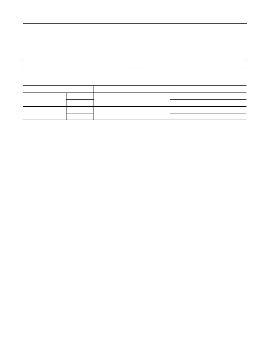
Drive Shaft

INFOID:0000000000957497

Axial end play

0.05 mm (0.002 in) or less

Joint 

Wheel side

Front final drive side

Grease quantity

Left side

77 – 97 g (2.72 – 3.42 oz)

95 – 105 g (3.35 – 3.70 oz)

Right side

113 – 123 g (3.99 – 4.34 oz)

Boots installed length

Left side

136 mm (5.35 in)

151.9 mm (5.98 in)

Right side

158 mm (6.22 in)

FL-1

ENGINE

C

D

E

F

G

H

I

J

K

L

M

SECTION 

FL

A

FL

N

O

P

CONTENTS

FUEL SYSTEM

PRECAUTION ...............................................

2

PRECAUTIONS ...................................................

2

General Precautions  .................................................

2

PREPARATION ............................................

3

PREPARATION ...................................................

3

Commercial Service Tools  ........................................

3

ON-VEHICLE MAINTENANCE .....................

4

FUEL SYSTEM  ....................................................

4

Inspection ..................................................................

4

Quick Connector  .......................................................

4

ON-VEHICLE REPAIR ..................................

5

FUEL LEVEL SENSOR UNIT, FUEL FILTER 
AND FUEL PUMP ASSEMBLY  ..........................

5

Exploded View  ..........................................................

5

Removal and Installation ...........................................

5

Inspection .................................................................

8

FUEL TANK  ......................................................

10

Exploded View .........................................................

10

Removal and Installation  .........................................

10

Inspection ................................................................

11

DISASSEMBLY AND ASSEMBLY ..............

13

FUEL LEVEL SENSOR UNIT, FUEL FILTER 
AND FUEL PUMP ASSEMBLY  ........................

13

Exploded View .........................................................

13

Disassembly ............................................................

13

Assembly .................................................................

14

SERVICE DATA AND SPECIFICATIONS 
(SDS) ............................................................

15

SERVICE DATA AND SPECIFICATIONS 
(SDS) .................................................................

15

Fuel Tank .................................................................

15

FL-2

< PRECAUTION >

PRECAUTIONS

PRECAUTION

PRECAUTIONS

General Precautions

INFOID:0000000000956364

WARNING:

When replacing fuel line parts, be sure to observe the following.
• Put a “CAUTION: FLAMMABLE” sign in the workshop.
• Be sure to work in a well ventilated area and furnish workshop with a CO

2

   fire extinguisher. 

• Do not smoke while servicing fuel system. Keep open flames and sparks away from the work area.

CAUTION:

• Use gasoline required by the regulations for octane number. Refer to 

GI-29, "FUEL : Unleaded Pre-

mium Gasoline Recommended"

.

• Before removing fuel line parts, perform out the following procedures:
- Put drained fuel in an explosion-proof container and put the lid on securely. Keep the container in

safe area.

- Release fuel pressure from the fuel lines. Refer to 

EC-543, "Inspection"

.

- Disconnect the battery cable from the negative terminal. 
• Always replace O-ring and clamps with new ones.
• Do not kink or twist tubes when they are being installed.
• Do not tighten hose clamps excessively to avoid damaging hoses. 
• After installing tubes, make sure there is no fuel leakage at connections in the following steps.
- Apply fuel pressure to fuel lines with turning ignition switch “ON” (with engine stopped). Then check

for fuel leaks at connections.

- Start engine and rev it up and check for fuel leaks at connections.
• Use only a genuine NISSAN fuel filler cap as a replacement. If an incorrect fuel filler cap is used, the

“MIL” may come on.

• For servicing “Evaporative Emission System” parts, refer to 

EC-77, "Component Parts Location"

.

• For servicing “On Board Refueling Vapor Recovery (ORVR)” parts, refer to 

EC-472, "Description"

.

PREPARATION

FL-3

< PREPARATION >

C

D

E

F

G

H

I

J

K

L

M

A

FL

N

P

O

PREPARATION

PREPARATION

Commercial Service Tools

INFOID:0000000000956365

Tool name

Description

Power tool

Loosening nuts and bolts

PBIC0190E


Content   ..  705  706  707  708   ..