Infiniti G35 (V35) Sedan. Manual - part 556


  Index      Infiniti     Infiniti G35 (V35) Sedan - service repair manual 2007 year


Search            


Content   ..  554  555  556  557   ..


Infiniti G35 (V35) Sedan. Manual - part 556


EC-370

< COMPONENT DIAGNOSIS >

[VQ35HR]

P1238, P2119 ELECTRIC THROTTLE CONTROL ACTUATOR

YES

>> Go to 

EC-370, "Diagnosis Procedure"

.

NO

>> INSPECTION END

Diagnosis Procedure

INFOID:0000000000956764

1.

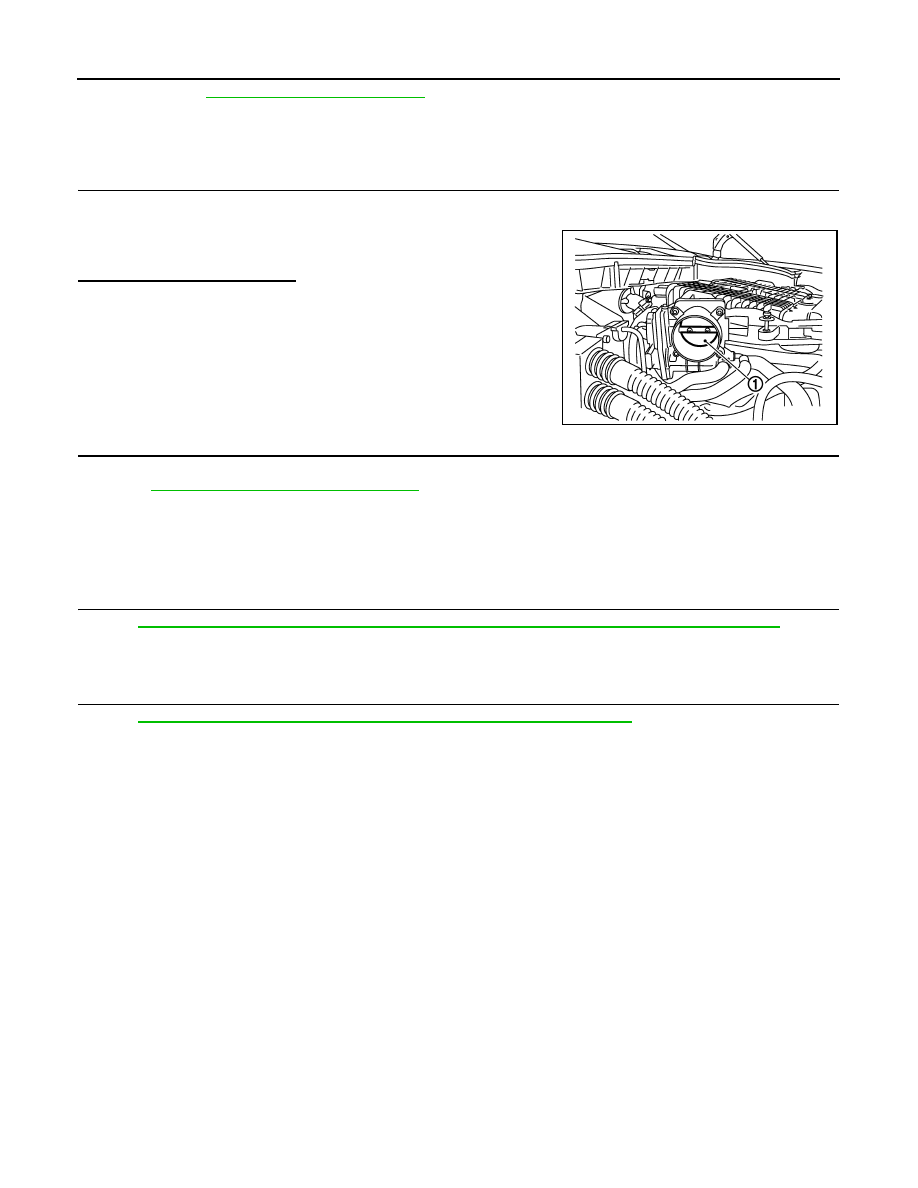
CHECK ELECTRIC THROTTLE CONTROL ACTUATOR VISUALLY

1.

Turn ignition switch OFF.

2.

Remove the intake air duct.

3.

Check if foreign matter is caught between the throttle valve (1)
and the housing.

Is the inspection result normal?

YES

>> GO TO 2.

NO

>> Remove the foreign matter and clean the electric throttle

control actuator inside.

2.

REPLACE ELECTRIC THROTTLE CONTROL ACTUATOR

1.

Replace malfunctioning electric throttle control actuator.

2.

Go to 

EC-370, "Special Repair Requirement"

.

>> INSPECTION END

Special Repair Requirement

INFOID:0000000000956765

1.

PERFORM THROTTLE VALVE CLOSED POSITION LEARNING

Refer to 

EC-18, "THROTTLE VALVE CLOSED POSITION LEARNING : Special Repair Requirement"

>> GO TO 2.

2.

PERFORM IDLE AIR VOLUME LEARNING

Refer to 

EC-18, "IDLE AIR VOLUME LEARNING : Special Repair Requirement"

>> END

JMBIA0025ZZ

P1239, P2135 TP SENSOR

EC-371

< COMPONENT DIAGNOSIS >

[VQ35HR]

C

D

E

F

G

H

I

J

K

L

M

A

EC

N

P

O

P1239, P2135 TP SENSOR

Description

INFOID:0000000000956766

Electric throttle control actuator consists of throttle control motor,
throttle position sensor, etc. The throttle position sensor responds to
the throttle valve movement. 
The throttle position sensor has two sensors. These sensors are a
kind of potentiometers which transform the throttle valve position into
output voltage, and emit the voltage signal to the ECM. In addition,
these sensors detect the opening and closing speed of the throttle
valve and feed the voltage signals to the ECM. The ECM judges the
current opening angle of the throttle valve from these signals and the
ECM controls the throttle control motor to make the throttle valve
opening angle properly in response to driving condition.

DTC Logic

INFOID:0000000000956767

DTC DETECTION LOGIC

NOTE:
If DTC P1239 or P2135 is displayed with DTC P0643, first perform the trouble diagnosis for DTC P0643.
Refer to 

EC-340, "DTC Logic"

.

DTC CONFIRMATION PROCEDURE

1.

PRECONDITIONING

If DTC Confirmation Procedure has been previously conducted, always turn ignition switch OFF and wait at
least 10 seconds before conducting the next test.
TESTING CONDITION:
Before performing the following procedure, confirm that battery voltage is more than 10V at idle.

>> GO TO 2.

2.

PERFORM DTC CONFIRMATION PROCEDURE

1.

Start engine and let it idle for 1 second.

2.

Check DTC.

Is DTC detected?

YES

>> Go to 

EC-371, "Diagnosis Procedure"

.

NO

>> INSPECTION END

Diagnosis Procedure

INFOID:0000000000956768

1.

CHECK GROUND CONNECTION

1.

Turn ignition switch OFF.

2.

Check ground connection M95. Refer to Ground Inspection in 

GI-42, "Circuit Inspection"

.

Is the inspection result normal?

YES

>> GO TO 2.

NO

>> Repair or replace ground connection.

2.

CHECK THROTTLE POSITION SENSOR POWER SUPPLY CIRCUIT-I

PBIB0145E

DTC No.

Trouble diagnosis name

DTC detecting condition

Possible cause

P1239

Throttle position sensor 
(bank 2) circuit range/
performance

Rationally incorrect voltage is sent to ECM 
compared with the signals from TP sensor 1 
and TP sensor 2.

• Harness or connector

(TP sensor 1 and 2 circuit is open or 
shorted.)

• Electric throttle control actuator

(TP sensor 1 and 2)

P2135

Throttle position sensor 
(bank 1) circuit range/
performance

EC-372

< COMPONENT DIAGNOSIS >

[VQ35HR]

P1239, P2135 TP SENSOR

1.

Disconnect electric throttle control actuator harness connector.

2.

Turn ignition switch ON.

3.

Check the voltage between electric throttle control actuator harness connector and ground.

Is the inspection result normal?

YES

>> GO TO 3.

NO

>> Repair open circuit or short to ground or short to power in harness or connectors.

3.

CHECK THROTTLE POSITION SENSOR GROUND CIRCUIT FOR OPEN AND SHORT

1.

Turn ignition switch OFF.

2.

Disconnect ECM harness connector.

3.

Check the continuity between electric throttle control actuator harness connector and ECM harness con-
nector.

4.

Also check harness for short to ground and short to power.

Is the inspection result normal?

YES

>> GO TO 4.

NO

>> Repair open circuit or short to ground or short to power in harness or connectors.

4.

CHECK THROTTLE POSITION SENSOR INPUT SIGNAL CIRCUIT FOR OPEN AND SHORT

1.

Check the continuity between electric throttle control actuator harness connector and ECM harness con-
nector.

2.

Also check harness for short to ground and short to power.

Is the inspection result normal?

YES

>> GO TO 5.

NO

>> Repair open circuit or short to ground or short to power in harness or connectors.

5.

CHECK THROTTLE POSITION SENSOR

Refer to 

EC-373, "Component Inspection"

.

Is the inspection result normal?

YES

>> GO TO 7.

NO

>> GO TO 6.

6.

REPLACE ELECTRIC THROTTLE CONTROL ACTUATOR

1.

Replace malfunctioning electric throttle control actuator.

2.

EC-373, "Special Repair Requirement"

DTC

Electric throttle control actuator

Ground

Voltage

Bank

Connector

Terminal

P1239

2

F27

1

Ground

Approx. 5V

P2135

1

F6

6

DTC

Electric throttle control actuator

ECM

Continuity

Bank

Connector

Terminal

Connector

Terminal

P1239

2

F27

4

F101

48

Existed

P2135

1

F6

3

40

DTC

Electric throttle control actuator

ECM

Continuity

Bank

Connector

Terminal

Connector

Terminal

P1239

2

F27

2

F101

31

Existed

3

35

P2135

1

F6

4

30

5

34

P1239, P2135 TP SENSOR

EC-373

< COMPONENT DIAGNOSIS >

[VQ35HR]

C

D

E

F

G

H

I

J

K

L

M

A

EC

N

P

O

>> INSPECTION END

7.

CHECK INTERMITTENT INCIDENT

Refer to 

GI-39, "Intermittent Incident"

.

>> INSPECTION END

Component Inspection

INFOID:0000000000956769

1.

CHECK THROTTLE POSITION SENSOR

1.

Turn ignition switch OFF.

2.

Reconnect all harness connectors disconnected.

3.

Perform 

EC-18, "THROTTLE VALVE CLOSED POSITION LEARNING : Special Repair Requirement"

.

4.

Turn ignition switch ON.

5.

Set selector lever to D (A/T) or 1st (M/T) position. 

6.

Check the voltage between ECM harness connector and ground.

Is the inspection result normal?

YES

>> INSPECTION END

NO

>> GO TO 2.

2.

REPLACE ELECTRIC THROTTLE CONTROL ACTUATOR

1.

Replace malfunctioning electric throttle control actuator.

2.

Go to 

EC-373, "Special Repair Requirement"

.

>> INSPECTION END

Special Repair Requirement

INFOID:0000000000956770

1.

PERFORM THROTTLE VALVE CLOSED POSITION LEARNING

Refer to 

EC-18, "THROTTLE VALVE CLOSED POSITION LEARNING : Special Repair Requirement"

>> GO TO 2.

2.

PERFORM IDLE AIR VOLUME LEARNING

Refer to 

EC-18, "IDLE AIR VOLUME LEARNING : Special Repair Requirement"

>> END

ECM

Ground

Condition

Voltage

Connector

Terminal

F101

30 [TP sensor 1 (bank 1)]
31 [TP sensor 1 (bank 2)]

Ground

Accelerator pedal

Fully released

More than 0.36V

Fully depressed

Less than 4.75V

34 [TP sensor 2 (bank 1)]
35 [TP sensor 2 (bank 2)]

Fully released

Less than 4.75V

Fully depressed

More than 0.36V


Content   ..  554  555  556  557   ..