Infiniti G35 (V35) Sedan. Manual - part 227
FRONT DISC BRAKE
BR-45
< ON-VEHICLE REPAIR >
C
D
E
G
H
I
J
K
L
M
A
B
BR
N
O
P
Cylinder Body
Check the inner wall of the cylinder for rust, wear, cracks or damage. Replace the cylinder if any abnormal
condition is detected.
CAUTION:
Always clean with new brake fluid. Never clean with mineral oil such as gasoline and light oil.
Torque Member
• Check the torque member for wear, cracks or damage. Replace the torque member if any abnormal condi-
tion is detected.
• Eliminate rust on the torque member. Replace them if rust is excessively attached.
Piston
Check the surface of the piston for rust, wear, cracks or damage. Replace the piston if any abnormal condition
is detected.
CAUTION:
A piston sliding surface is plated. Never polish with sandpaper.
Location Pin, Protector and Bushing
Check the location pin, protector and bushing for rust, wear, cracks or damage. Replace the parts if any abnor-
mal condition is detected.
Sliding Pin and Sliding Pin Boot
Check the sliding pin and sliding boots for rust, wear, cracks or damage. Replace the parts if any abnormal
condition is detected.
ADJUSTMENT AFTER INSTALLATION
Brake Burnishing Procedure
Burnish contact surfaces between disc rotors and pads according to following procedure after refinishing or
replacing disc rotor, or if a soft pedal occurs at very low mileage.
CAUTION:
• Be careful of vehicle speed because the brake does not operate easily until pad and disc rotor are
securely fitted.
• Only perform this procedure under safe road and traffic conditions. Use extreme caution.
1.
Drive vehicle on straight, flat road.
2.
Depress brake pedal with the power to stop vehicle within 3 to 5 seconds until the vehicle stops.
3.
Drive without depressing brake for a few minutes to cool the brake.
4.
Repeat steps 1 to 3 until pad and disc rotor are securely fitted.
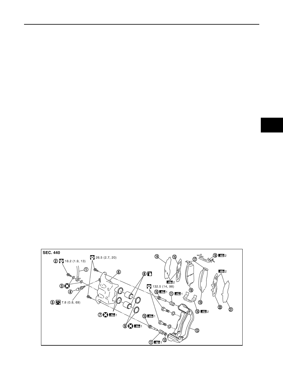
BRAKE CALIPER ASSEMBLY (2 PISTON TYPE)
BRAKE CALIPER ASSEMBLY (2 PISTON TYPE) : Exploded View
INFOID:0000000000958457
JPFIA0026GB