Infiniti G35 (V35) Sedan. Manual - part 99


  Index      Infiniti     Infiniti G35 (V35) Sedan - service repair manual 2007 year


Search            


Content   ..  97  98  99  100   ..


Infiniti G35 (V35) Sedan. Manual - part 99


AV-168

< COMPONENT DIAGNOSIS >

[BOSE AUDIO WITHOUT NAVIGATION]

RGB (G: GREEN) SIGNAL CIRCUIT

RGB (G: GREEN) SIGNAL CIRCUIT

Description

INFOID:0000000000964667

Transmit the image displayed with AV control unit with RGB signal to the display unit.

Diagnosis Procedure

INFOID:0000000000964668

1.

CHECK CONTINUITY RGB (G: GREEN) SIGNAL CIRCUIT

1.

Turn ignition switch OFF.

2.

Disconnect display unit connector and AV control unit connector.

3.

Check continuity between display unit harness connector terminal 6 and AV control unit harness connec-
tor terminal 39.

4.

Check continuity between display unit harness connector terminal 6 and ground.

Is inspection result OK?

YES

>> GO TO 2.

NO

>> Repair harness or connector.

2.

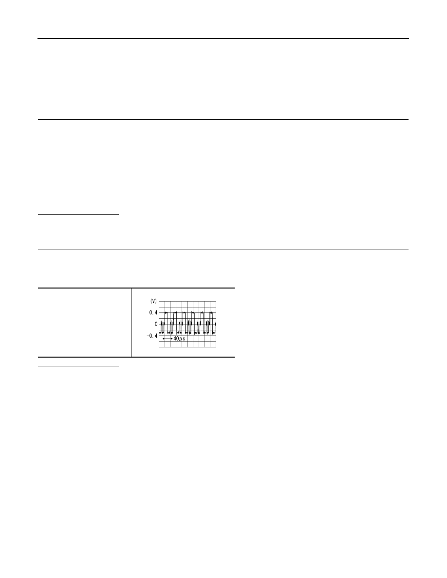
CHECK RGB (G: GREEN) SIGNAL

1.

Connect display unit connector and AV control unit connector.

2.

Turn ignition switch ON.

3.

Check signal between display unit harness connector terminal 6 and ground.

Is inspection result OK?

YES

>> Replace display unit.

NO

>> Replace AV control unit.

6 - 39

: Continuity should exist.

6 - Ground

: Continuity should not exist.

6 - Ground

SKIB2236J

AV

RGB (B: BLUE) SIGNAL CIRCUIT

AV-169

< COMPONENT DIAGNOSIS >

[BOSE AUDIO WITHOUT NAVIGATION]

C

D

E

F

G

H

I

J

K

L

M

B

N

A

O

P

RGB (B: BLUE) SIGNAL CIRCUIT

Description

INFOID:0000000000964669

Transmit the image displayed with AV control unit with RGB signal to the display unit.

Diagnosis Procedure

INFOID:0000000000964670

1.

CHECK CONTINUITY RGB (B: BLUE) SIGNAL CIRCUIT

1.

Turn ignition switch OFF.

2.

Disconnect display unit connector and AV control unit connector.

3.

Check continuity between display unit harness connector terminal 18 and AV control unit harness connec-
tor terminal 38.

4.

Check continuity between display unit harness connector terminal 18 and ground.

Is inspection result OK?

YES

>> GO TO 2.

NO

>> Repair harness or connector.

2.

CHECK RGB (B: BLUE) SIGNAL

1.

Connect display unit connector and AV control unit connector.

2.

Turn ignition switch ON.

3.

Check signal between display unit harness connector terminal 18 and ground.

Is inspection result OK?

YES

>> Replace display unit.

NO

>> Replace AV control unit.

18 - 38

: Continuity should exist.

18 - Ground

: Continuity should not exist.

18 - Ground

SKIB2237J

AV-170

< COMPONENT DIAGNOSIS >

[BOSE AUDIO WITHOUT NAVIGATION]

RGB SYNCHRONIZING SIGNAL CIRCUIT

RGB SYNCHRONIZING SIGNAL CIRCUIT

Description

INFOID:0000000000964671

Transmit the RGB synchronizing signal to the display unit so as to synchronize the RGB image displayed with
AV control unit.

Diagnosis Procedure

INFOID:0000000000964672

1.

CHECK CONTINUITY RGB SYNCHRONIZING SIGNAL CIRCUIT

1.

Turn ignition switch OFF.

2.

Disconnect display unit connector and AV control unit connector.

3.

Check continuity between display unit harness connector terminal 19 and AV control unit harness connec-
tor terminal 41.

4.

Check continuity between display unit harness connector terminal 19 and ground.

Is inspection result OK?

YES

>> GO TO 2.

NO

>> Repair harness or connector.

2.

CHECK RGB SYNCHRONIZING SIGNAL

1.

Connect display unit connector and AV control unit connector.

2.

Turn ignition switch ON.

3.

Check signal between display unit harness connector terminal 19 and ground.

Is inspection result OK?

YES

>> Replace display unit.

NO

>> Replace AV control unit.

19 - 41

: Continuity should exist.

19 - Ground

: Continuity should not exist.

19 - Ground

SKIB3603E

AV

RGB AREA (YS) SIGNAL CIRCUIT

AV-171

< COMPONENT DIAGNOSIS >

[BOSE AUDIO WITHOUT NAVIGATION]

C

D

E

F

G

H

I

J

K

L

M

B

N

A

O

P

RGB AREA (YS) SIGNAL CIRCUIT

Description

INFOID:0000000000964673

Transmits the display area of RGB image displayed by AV control unit with RGB area (YS) signal to display
unit.

Diagnosis Procedure

INFOID:0000000000964674

1.

CHECK CONTINUITY RGB AREA (YS) SIGNAL CIRCUIT

1.

Turn ignition switch OFF.

2.

Disconnect display unit connector and AV control unit connector.

3.

Check continuity between display unit harness connector terminal 9 and AV control unit harness connec-
tor terminal 43.

4.

Check continuity between display unit harness connector terminal 9 and ground.

Is inspection result OK?

YES

>> GO TO 2.

NO

>> Repair harness or connector.

2.

CHECK RGB SYNCHRONIZING SIGNAL

1.

Connect display unit connector and AV control unit connector.

2.

Turn ignition switch ON.

3.

Check signal between display unit harness connector terminal 9 and ground.

Is inspection result OK?

YES

>> Replace display unit.

NO

>> Replace AV control unit.

9 - 43

: Continuity should exist.

9 - Ground

: Continuity should not exist.

9 - Ground

At RGB image displayed

: Approx. 5 V

At rear view camera image displayed

PKIB4948J


Content   ..  97  98  99  100   ..