Infiniti G35 (V35) Sedan. Manual - part 66


  Index      Infiniti     Infiniti G35 (V35) Sedan - service repair manual 2007 year


Search            


Content   ..  64  65  66  67   ..


Infiniti G35 (V35) Sedan. Manual - part 66


AV-36

< COMPONENT DIAGNOSIS >

[BASE AUDIO WITHOUT NAVIGATION]

U1243 DISPLAY UNIT

Is inspection result OK?

YES

>> GO TO 4.

NO

>> Replace AV control unit.

4.

CHECK COMMUNICATION SIGNAL

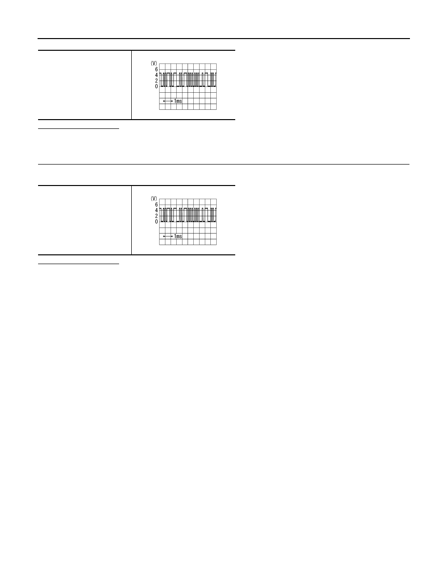
Check signal between display unit harness connector terminal 22 and ground.

Is inspection result OK?

YES

>> INSPECTION END

NO

>> Replace display unit.

11 - Ground

:

PKIB5039J

22 - Ground

PKIB5039J

AV

U1255 SATELLITE RADIO TUNER

AV-37

< COMPONENT DIAGNOSIS >

[BASE AUDIO WITHOUT NAVIGATION]

C

D

E

F

G

H

I

J

K

L

M

B

N

A

O

P

U1255 SATELLITE RADIO TUNER

Description

INFOID:0000000000964545

DTC Logic

INFOID:0000000000964546

Diagnosis Procedure

INFOID:0000000000964547

1.

CHECK SATELLITE RADIO TUNER POWER SUPPLY AND GROUND CIRCUIT

Check satellite radio tuner power supply and ground circuit. Refer to 

AV-41, "SATELLITE RADIO TUNER :

Diagnosis Procedure"

.

Is inspection result OK?

YES

>> INSPECTION END

NO

>> Repair malfunctioning parts.

Part name

Description

SATELLITE RADIO TUNER

• Inputs the satellite radio signal from satellite radio antenna and outputs it to 

the AV control unit.

• It is controlled with the communication (communication signal, request sig-

nal) from AV control unit.

DTC

Display contents of 

CONSULT-III

DTC Detection Condition

Possible causes

U1255

SAT CONN
[U1255]

The satellite radio tuner power supply and ground circuit 
malfunction is detected

Satellite radio tuner power supply and 
ground circuit

AV-38

< COMPONENT DIAGNOSIS >

[BASE AUDIO WITHOUT NAVIGATION]

U1300 AV COMM CIRCUIT

U1300 AV COMM CIRCUIT

Description

INFOID:0000000000964548

U1300 is indicated when malfunction occurs in communication signal of multi AV system. Indicated simulta-
neously, without fail, with the malfunction of control units connected to AV control unit with communication line.
Determine the possible malfunction cause from the table below.

Self-diagnosis results display item

DTC

Display contents of 

CONSULT-III

DTC Detection Condition

Possible causes

U1300
U1240

• AV COMM CIRCUIT

[U1300]

• SWITCH CONN

[U1240]

• Multifunction switch power supply and ground circuit 

malfunction is detected

• A malfunction is detected in communication circuit be-

tween AV control unit and multifunction switch

• A malfunction is detected in communication signal be-

tween AV control unit and multifunction switch

• Multifunction switch power supply 

and ground circuits

• Communication circuit between AV 

control unit and multifunction 
switch

AV

POWER SUPPLY AND GROUND CIRCUIT

AV-39

< COMPONENT DIAGNOSIS >

[BASE AUDIO WITHOUT NAVIGATION]

C

D

E

F

G

H

I

J

K

L

M

B

N

A

O

P

POWER SUPPLY AND GROUND CIRCUIT

AV CONTROL UNIT

AV CONTROL UNIT : Diagnosis Procedure

INFOID:0000000000964549

1.

CHECK FUSE

Check for blown fuses.

Is inspection result OK?

YES

>> GO TO 2.

NO

>> Be sure to eliminate cause of malfunction before installing new fuse. 

2.

CHECK POWER SUPPLY CIRCUIT

Check voltage between AV control unit harness connectors and ground.

Is inspection result OK?

YES

>> GO TO 3.

NO

>> Check harness between AV control unit and fuse.

3.

CHECK GROUND CIRCUIT

1.

Turn ignition switch OFF.

2.

Disconnect AV control unit connectors.

3.

Check continuity between AV control unit harness connectors and ground.

Is inspection result OK?

YES

>> INSPECTION END

NO

>> Repair harness or connector.

DISPLAY UNIT

DISPLAY UNIT : Diagnosis Procedure

INFOID:0000000000964550

1.

CHECK POWER SUPPLY CIRCUIT (DISPLAY SIDE)

Check voltage between Display unit harness connector and ground.

Is inspection result OK?

YES

>> GO TO 4.

NO

>> GO TO 2.

Power source

Fuse No.

Battery

34

Ignition switch ACC or ON

19

Ignition switch ON or START 

3

Signal name

Connector No.

Terminal No.

Ignition switch position

Value (Approx.)

Battery power supply

M81

19

OFF

12 V

ACC power supply

M81

7

ACC

12 V

Ignition signal

M85

104

ON

12 V

Signal name

Connector No.

Terminal No.

Ignition switch position

Continuity 

Ground

M81

20

OFF

Continuity should exist.

M85

85

Signal name

Connector No.

Terminal No.

Ignition switch position

Value (Approx.)

Inverter VCC

M71

2

ACC

9 V

Signal VCC

3


Content   ..  64  65  66  67   ..