Infiniti G35 (V35). Manual - part 561


  Index      Infiniti     Infiniti G35 (V35) Coupe - service repair manual 2007 year


Search            


Content   ..  559  560  561  562   ..


Infiniti G35 (V35). Manual - part 561


LAN-4

[CAN FUNDAMENTAL]

SYSTEM DESCRIPTION

SYSTEM DESCRIPTION

PFP:00000

CAN Communication System

NKS004IQ

CAN communication is a multiplex communication system. This enables the system to transmit and
receive large quantities of data at high speed by connecting control units with two communication lines
(CAN-H and CAN-L).

Control units on the CAN network transmit signals using the CAN communication control circuit. They
receive only necessary signals from other control units to operate various functions.

CAN communication lines adopt twisted-pair line style (two lines twisted) for noise immunity.
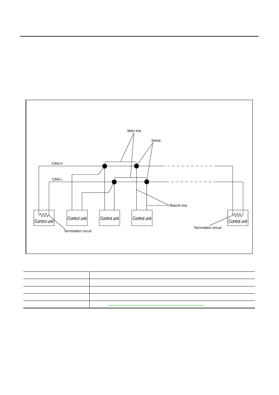
SYSTEM DIAGRAM

Each control unit passes an electric current to the termination circuits when transmitting CAN communication
signal. The termination circuits produce an electrical potential difference between CAN-H and CAN-L. CAN
communication system transmits and receives CAN communication signals by the potential difference.

SKIB8887E

Component

Description

Main line

CAN communication line between splices

Branch line

CAN communication line between splice and a control unit

Splice

A point connecting a branch line with a main line

Termination circuit

Refer to 

LAN-5, "CAN COMMUNICATION CONTROL CIRCUIT"

 .

SYSTEM DESCRIPTION

LAN-5

[CAN FUNDAMENTAL]

C

D

E

F

G

H

I

J

L

M

A

B

LAN

CAN COMMUNICATION CONTROL CIRCUIT

*: These are the only control units wired with both ends of CAN communication system.

SKIB8713E

Component

System description

CAN controller

It controls CAN communication signal transmission and reception, error detection, etc.

Transceiver IC

It converts digital signal into CAN communication signal, and CAN communication signal into digi-
tal signal.

Noise filter

It eliminates noise of CAN communication signal.

Termination circuit

*

(Resistance of approx. 120 

)

It produces potential difference.

LAN-6

[CAN FUNDAMENTAL]

SYSTEM DESCRIPTION

Diag on CAN

NKS004IR

DESCRIPTION

“Diag on CAN” is a diagnosis using CAN communication instead of previous DDL1 and DDL2 communication
line, between control unit and diagnosis unit.

SYSTEM DIAGRAM

SKIB8714E

Name

Harness

Description

DDL1

Tx
Rx

It is used for trouble diagnosis. (CAN-H and CAN-L are used for controlling)

DDL2

K-LINE

It is used for trouble diagnosis. (CAN-H and CAN-L are used for controlling)

Diag on CAN

CAN-H
CAN-L

It is used for trouble diagnosis and control.

TROUBLE DIAGNOSIS

LAN-7

[CAN FUNDAMENTAL]

C

D

E

F

G

H

I

J

L

M

A

B

LAN

TROUBLE DIAGNOSIS

PFP:00004

Condition of Error Detection

NKS004IS

“U1000” or “U1001” is indicated on SELF-DIAG RESULTS on CONSULT-II if CAN communication signal is not
transmitted or received between units for 2 seconds or more.

CAN COMMUNICATION SYSTEM ERROR

CAN communication line open (CAN-H, CAN-L, or both)

CAN communication line short (ground, between CAN communication lines, other harnesses)

Error of CAN communication control circuit of the unit connected to CAN communication line

WHEN INDICATED “U1000” OR “U1001” IS INDICATED EVEN THOUGH CAN COMMUNICA-
TION SYSTEM IS NORMAL

CONSULT-II CONVERTER not connected: Error may be detected by the self-diagnosis when not using
CONSULT-II CONVERTER (Depending on the control unit which carries out CAN communication).

Removal/installation of parts: Error may be detected when removing and installing CAN communication
unit and related parts while turning the ignition switch ON. (A DTC except for CAN communication may be
detected.)

Fuse blown out (removed): CAN communication of the unit may cease.

Voltage drop: Error may be detected if voltage drops due to discharged battery when turning the ignition
switch ON (Depending on the control unit which carries out CAN communication).

Error may be detected if the power supply circuit of the control unit, which carries out CAN communica-
tion, malfunctions (Depending on the control unit which carries out CAN communication).

Error may be detected if reprogramming is not completed normally.

NOTE:
CAN communication system is normal if “U1000” or “U1001” is indicated on SELF-DIAG RESULTS of CON-
SULT-II under the above conditions. Erase the memory of the self-diagnosis of each unit.


Content   ..  559  560  561  562   ..