Infiniti FX35 / FX45. Manual - part 862


  Index      Infiniti     Infiniti FX35 / FX45 (S50) - service repair manual 2008 year


Search            


Content   ..  860  861  862  863   ..


Infiniti FX35 / FX45. Manual - part 862


NOISE, VIBRATION AND HARSHNESS (NVH) TROUBLESHOOTING

PR-3

< SERVICE INFORMATION >

C

E

F

G

H

I

J

K

L

M

A

B

PR

N

O

P

NOISE, VIBRATION AND HARSHNESS (NVH) TROUBLESHOOTING

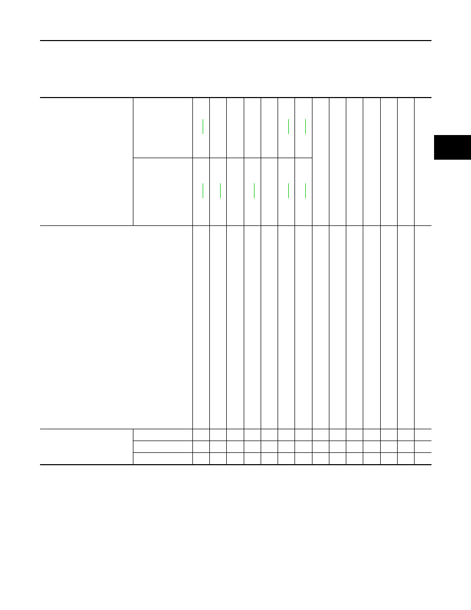
NVH Troubleshooting Chart

INFOID:0000000001327465

Use the chart below to help you find the cause of the symptom. If necessary, repair or replace these parts.

×

: Applicable

Reference page

Front

PR-4

PR-4

PR-4

NVH in FFD an

d RF

se

ct

ion

NVH in F

AX, RAX

, FS

U,

 an

d RS

se

ct

ion

NVH in WT

 se

ct

io

n

NVH in WT

 se

ct

io

n

NVH in RAX 

section

NVH in BR section

NVH in PS 

section

Rear

PR-7

PR-9

PR-8

PR-7

PR-9

Possible cause and SUSPECTED PARTS

Un

ev

en

 rot

a

ti

ng

 to

rqu

e

Cen

ter bea

rin

g

 i

m

p

rop

er ins

ta

lla

tio

n

Exc

e

s

s

iv

e

 c

e

n

ter 

be

arin

ax

ia

l e

n

d

 pl

ay

Ce

nt

e

b

e

a

ri

ng

 mou

n

ti

n

g

 (in

su

lat

or) c

rack

s,

 da

ma

ge

 or de

te

ri

ora

tio

n

Ex

ce

ssi

ve

 jo

in

t an

gl

e

Ro

tat

ion

 i

m

ba

la

nc

e

Ex

ce

ssi

ve

 run

o

u

t

DIFFERE

N

T

IAL

AXLE

 AND SUSPE

N

S

ION

TIRE

ROA

D

 WHEEL

DR

IVE SHAF

T

BRAKE

STEERI

N

G

Symptom

Noise

×

×

×

×

×

×

×

×

×

×

×

×

×

×

Shake

×

×

×

×

×

×

×

×

Vibration

×

×

×

×

×

×

×

×

×

×

×

PR-4

< SERVICE INFORMATION >

FRONT PROPELLER SHAFT

FRONT PROPELLER SHAFT

On-Vehicle Inspection

INFOID:0000000001327466

APPEARANCE AND NOISE INSPECTION

Check the propeller shaft tube surface for dents or cracks. If damaged, replace propeller shaft assembly.

PROPELLER SHAFT VIBRATION

If vibration is present at high speed, inspect propeller shaft runout first.

1.

Measure propeller shaft runout at runout measuring point by
rotating final drive companion flange with hands. For measuring
point, refer to "Propeller Shaft Runout Measuring Point".

2.

If runout still exceeds specifications, separate propeller shaft at
final drive companion flange; then rotate companion flange 90,
180, 270 degrees and install propeller shaft.

3.

Check runout again. If runout still exceeds specifications,
replace propeller shaft assembly. 

4.

Check the vibration by driving vehicle.

Propeller Shaft Runout Measuring Point

Propeller shaft runout measuring point (Point “ ”)

Component

INFOID:0000000001327467

Removal and Installation

INFOID:0000000001327468

REMOVAL

1.

Remove the front and rear engine undercover with a power tool.

2.

Remove the front cross bar with a power tool. Refer to 

FSU-5

.

3.

Remove the exhaust front tube bracket with a power tool. Refer to 

EX-3

.

4.

Disconnect the heated oxygen sensor harness connector.

Propeller shaft runout limit

: 0.8 mm (0.031 in)

SDIA1759E

Dimension

A: 381.5 mm (15.01 in)

PDIA0768J

1.

Propeller shaft assembly

2.

O-ring

Refer to 

GI-8, "Component"

, for the symbols in the figure.

PDIA1215E

FRONT PROPELLER SHAFT

PR-5

< SERVICE INFORMATION >

C

E

F

G

H

I

J

K

L

M

A

B

PR

N

O

P

5.

Remove the exhaust front tube mounting nuts with a power tool. Refer to 

EX-3

.

6.

Remove the right bank three way catalyst with a power tool. Refer to 

EM-26, "Removal and Installation"

(VQ35DE), 

EM-179, "Removal and Installation"

 (VK45DE).

7.

Remove the power steering piping mounting bolts. Refer to 

PS-

37

.

8.

Remove the power steering gear box fixing bolts to secure work-
ing area for removal of propeller shaft. Refer to 

PS-17

.

CAUTION:

Be careful not to damage the steering gear box piping dur-
ing removal.

9.

Put matching marks onto propeller shaft flange yoke and final
drive companion flange.

CAUTION:

For matching mark, use paint. Never damage propeller shaft
flange and companion flange. 

10. Remove the propeller shaft fixing bolts.

11. Set the transmission jack at the transfer, remove rear engine

mounting bolts, and then lower transmission jack about 40 - 50
mm (0.16 - 0.21 in).

12. Remove propeller shaft from the front final drive and transfer.

INSPECTION

• Inspect propeller shaft runout at measuring point. If runout

exceeds specifications, replace propeller shaft assembly. For mea-
suring point, refer to 

PR-4, "On-Vehicle Inspection"

.

SDIA1516E

SDIA1517E

SDIA1518E

Propeller shaft runout limit

: 0.8 mm (0.031 in)

SPD106

PR-6

< SERVICE INFORMATION >

FRONT PROPELLER SHAFT

• As shown in the figure, while fixing yoke on one side, check axial

play of joint. If outside the standard, replace propeller shaft assem-
bly. 

• Check propeller shaft for bend and damage. If damage is detected,

replace propeller shaft assembly.

CAUTION:

Never disassemble joints.

INSTALLATION

Note the following, install in the reverse order of removal.
• Align matching marks to install propeller shaft to final drive com-

panion flange, and then tighten to specified torque. Refer to 

PR-4,

"Component"

.

CAUTION:

Never reuse the bolts.

• After assembly, perform a driving test to check propeller shaft

vibration. If vibration occurred, separate propeller shaft from final
drive or transfer. Reinstall companion flange after rotating it by 90,
180, 270 degrees. Then perform driving test and check propeller
shaft vibration again at each point.

Journal axial play 

: 0 mm (0 in)

PDA0005D

SDIA1517E


Content   ..  860  861  862  863   ..