Infiniti FX35 / FX45. Manual - part 672
TIMING CHAIN
EM-205
< SERVICE INFORMATION >
[VK45DE]
C
D
E
F
G
H
I
J
K
L
M
A
EM
N
P
O
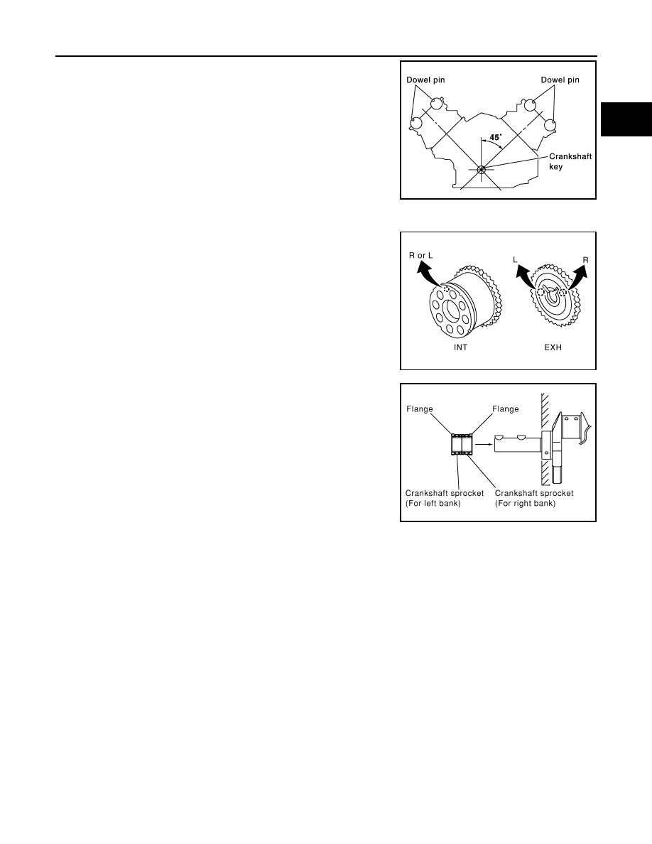
1.
Make sure that crankshaft key and dowel pin of each camshaft
are located as shown in the figure. (No. 1 cylinder at compres-
sion TDC)
NOTE:
Though camshaft does not stop at the position as shown in the
figure, for the placement of cam nose, it is generally accepted
camshaft is placed for the same direction of the figure.
2.
Install camshaft sprockets.
• Install onto correct side by checking with identification mark on
surface.
• Install camshaft sprocket (EXH) by selectively using the
groove of dowel pin according to the bank. (Common part
used for both banks.)
• Lock the hexagonal part of camshaft in the same procedure as
for removal, and tighten mounting bolts.
3.
Install crankshaft sprockets for both banks.
• Install each crankshaft sprocket so that its flange side (the
larger diameter side without teeth) faces in the direction shown
in the figure.
NOTE:
The same parts are used but facing directions are different.
Camshaft dowel pin
: At cylinder head upper face side in each bank
Crankshaft key
: At cylinder head side of left bank
SBIA0356E
PBIC2345E
PBIC0057E