Infiniti FX35 / FX45. Manual - part 532


  Index      Infiniti     Infiniti FX35 / FX45 (S50) - service repair manual 2008 year


Search            


Content   ..  530  531  532  533   ..


Infiniti FX35 / FX45. Manual - part 532


DTC P0222, P0223 TP SENSOR

EC-889

< SERVICE INFORMATION >

[VK45DE]

C

D

E

F

G

H

I

J

K

L

M

A

EC

N

P

O

DTC P0222, P0223 TP SENSOR

Component Description

INFOID:0000000001326720

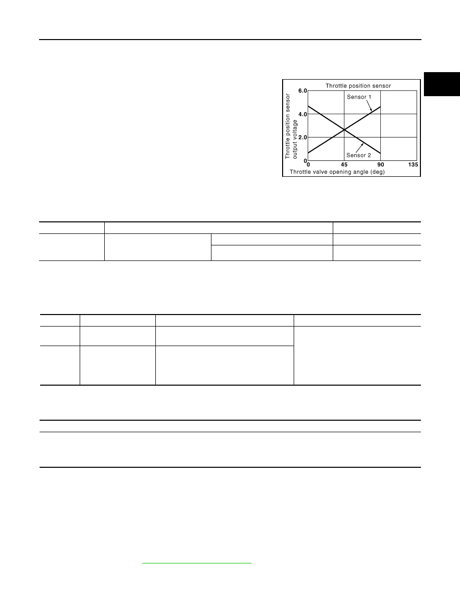
Electric throttle control actuator consists of throttle control motor,
throttle position sensor, etc. The throttle position sensor responds to
the throttle valve movement.
The throttle position sensor has the two sensors. These sensors are
a kind of potentiometers which transform the throttle valve position
into output voltage, and emit the voltage signal to the ECM. In addi-
tion, these sensors detect the opening and closing speed of the
throttle valve and feed the voltage signals to the ECM. The ECM
judges the current opening angle of the throttle valve from these sig-
nals and the ECM controls the throttle control motor to make the
throttle valve opening angle properly in response to driving condi-
tion.

CONSULT-III Reference Value in Data Monitor Mode

INFOID:0000000001326721

Specification data are reference values.

*: Throttle position sensor 2 signal is converted by ECM internally. Thus, it differs from ECM terminal voltage signal.

On Board Diagnosis Logic

INFOID:0000000001326722

These self-diagnoses have the one trip detection logic.

FAIL-SAFE MODE

When the malfunction is detected, ECM enters fail-safe mode and the MIL lights up.

DTC Confirmation Procedure

INFOID:0000000001326723

NOTE:
If DTC Confirmation Procedure has been previously conducted, always turn ignition switch OFF and wait at
least 10 seconds before conducting the next test.
TESTING CONDITION:
Before performing the following procedure, confirm that battery voltage is more than 8V at idle.

1.

Start engine and let it idle for 1 second.

2.

Check DTC.

3.

If DTC is detected, go to 

EC-891, "Diagnosis Procedure"

.

PBIB0145E

MONITOR ITEM

CONDITION

SPECIFICATION

TP SEN 1-B1
TP SEN 2-B1*

• Ignition switch: ON

(Engine stopped)

• Selector lever: D

Accelerator pedal: Fully released

More than 0.36V

Accelerator pedal: Fully depressed

Less than 4.75V

DTC No.

Trouble diagnosis name

DTC detecting condition

Possible cause

P0222
0222

Throttle position sensor 
1 circuit low input

An excessively low voltage from the TP sensor 
1 is sent to ECM.

• Harness or connectors

(TP sensor 1 circuit is open or shorted.)
(APP sensor 2 circuit is shorted.)

• Electric throttle control actuator

(TP sensor 1)

• Accelerator pedal position sensor

(APP sensor 2)

P0223
0223

Throttle position sensor 
1 circuit high input

An excessively high voltage from the TP sensor 
1 is sent to ECM.

Engine operation condition in fail-safe mode

The ECM controls the electric throttle control actuator in regulating the throttle opening in order for the idle position to be within +10 
degrees.
The ECM regulates the opening speed of the throttle valve to be slower than the normal condition.
So, the acceleration will be poor. 

EC-890

< SERVICE INFORMATION >

[VK45DE]

DTC P0222, P0223 TP SENSOR

Wiring Diagram

INFOID:0000000001326724

Specification data are reference values and are measured between each terminal and ground.

CAUTION:

Do not use ECM ground terminals when measuring input/output voltage. Doing so may result in dam-
age to the ECM's transistor. Use a ground other than ECM terminals, such as the ground.

TBWM1335E

DTC P0222, P0223 TP SENSOR

EC-891

< SERVICE INFORMATION >

[VK45DE]

C

D

E

F

G

H

I

J

K

L

M

A

EC

N

P

O

Diagnosis Procedure

INFOID:0000000001326725

1.

CHECK GROUND CONNECTIONS

1.

Turn ignition switch OFF.

2.

Loosen and retighten three ground screws on the body.
Refer to 

EC-723, "Ground Inspection"

.

OK or NG

OK

>> GO TO 2.

NG

>> Repair or replace ground connections.

2.

CHECK THROTTLE POSITION SENSOR 1 POWER SUPPLY CIRCUIT-I

TER-

MI-

NAL 

NO.

WIRE 

COLOR

ITEM

CONDITION

DATA (DC Voltage)

47

L

Sensor power supply (Throt-
tle position sensor)

[Ignition switch: ON]

Approximately 5V

50

W

Throttle position sensor 1

[Ignition switch: ON]
• Engine stopped
• Selector lever: D
• Accelerator pedal: Fully released

More than 0.36V

[Ignition switch: ON]
• Engine stopped
• Selector lever: D
• Accelerator pedal: Fully depressed

Less than 4.75V

66

B

Sensor ground
(Throttle position sensor)

[Engine is running]
• Warm-up condition
• Idle speed

Approximately 0V

69

R

Throttle position sensor 2

[Ignition switch: ON]
• Engine stopped
• Selector lever: D
• Accelerator pedal: Fully released

Less than 4.75V

[Ignition switch: ON]
• Engine stopped
• Selector lever: D
• Accelerator pedal: Fully depressed

More than 0.36V

91

G

Sensor power supply
(APP sensor 2)

[Ignition switch: ON]

Approximately 5V

PBIB2195E

EC-892

< SERVICE INFORMATION >

[VK45DE]

DTC P0222, P0223 TP SENSOR

1.

Disconnect electric throttle control actuator (1) harness connec-
tor.

2.

Turn ignition switch ON.

3.

Check voltage between electric throttle control actuator terminal
6 and ground with CONSULT-III or tester.

OK or NG

OK

>> GO TO 7.

NG

>> GO TO 3.

3.

CHECK THROTTLE POSITION SENSOR 1 POWER SUPPLY CIRCUIT-II

1.

Turn ignition switch OFF.

2.

Disconnect ECM harness connector.

3.

Check harness continuity between electric throttle control actuator terminal 6 and ECM terminal 47.
Refer to Wiring Diagram.

OK or NG

OK

>> GO TO 4.

NG

>> Repair open circuit.

4.

CHECK THROTTLE POSITION SENSOR 1 POWER SUPPLY CIRCUIT-III

Check harness for short to power and short to ground, between the following terminals.

OK or NG

OK

>> GO TO 5.

NG

>> Repair short to ground or short to power in harness or connectors.

5.

CHECK APP SENSOR

Refer to 

EC-1115, "Component Inspection"

.

OK or NG

OK

>> GO TO 11.

NG

>> GO TO 6.

6.

REPLACE ACCELERATOR PEDAL ASSEMBLY

1.

Replace accelerator pedal assembly.

2.

Perform 

EC-662, "Accelerator Pedal Released Position Learning"

.

3.

Perform 

EC-663, "Throttle Valve Closed Position Learning"

.

4.

Perform 

EC-663, "Idle Air Volume Learning"

.

PBIB3232E

Voltage: Approximately 5V

PBIB3250E

Continuity should exist.

ECM terminal

Sensor terminal

Reference Wiring Diagram

47

Electric throttle control actuator terminal 6

EC-890

91

APP sensor terminal 4

EC-1111


Content   ..  530  531  532  533   ..