Infiniti FX35 / FX45. Manual - part 281


  Index      Infiniti     Infiniti FX35 / FX45 (S50) - service repair manual 2008 year


Search            


Content   ..  279  280  281  282   ..


Infiniti FX35 / FX45. Manual - part 281


CO-54

< SERVICE INFORMATION >

[VK45DE]

THERMOSTAT AND WATER CONTROL VALVE

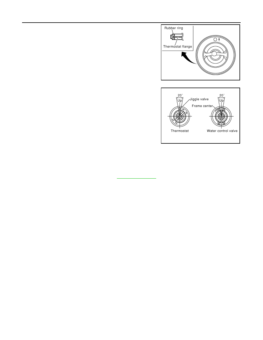
• Install thermostat and water control valve with the whole circumfer-

ence of each flange part fit securely inside rubber ring. (The exam-
ple in the figure shows thermostat.) 

• Install thermostat with jiggle valve facing upwards. (The position

deviation may be within the range of 

±

10 degrees)

• Install water control valve with the up-mark facing up and the frame

center part facing upwards. (The position deviation may be within
the range of 

±

10 degrees)

Water Outlet Pipe and Heater Pipe

First apply a neutral detergent to O-rings, then quickly insert the insertion parts of the water outlet pipe and
heater pipe into the installation holes.

INSPECTION AFTER INSTALLATION

• Check for leaks of engine coolant using radiator cap tester adapter (commercial service tool) and radiator

cap tester (commercial service tool). Refer to 

CO-37, "Inspection"

.

• Start and warm up engine. Visually check if there is no leaks of engine coolant.

PBIC0157E

PBIC0158E

SERVICE DATA AND SPECIFICATIONS (SDS)

CO-55

< SERVICE INFORMATION >

[VK45DE]

C

D

E

F

G

H

I

J

K

L

M

A

CO

N

P

O

SERVICE DATA AND SPECIFICATIONS (SDS)

Standard and Limit

INFOID:0000000001325886

ENGINE COOLANT CAPACITY (APPROXIMATE)

Unit: 

 (US qt, Imp qt)

RADIATOR

Unit: kPa (kg/cm

2

, psi)

THERMOSTAT

WATER CONTROL VALVE

Engine coolant capacity [With reservoir tank at (“MAX” level)]

10.0 (10-5/8, 8-3/4)

Reservoir tank engine coolant capacity (at “MAX” level)

0.8  (7/8, 3/4)

Radiator cap relief pressure

Standard

78 - 98 (0.8 - 1.0, 11 - 14)

Limit

59 (0.6, 9)

Leakage testing pressure

157 (1.6, 23)

Valve opening temperature

80 - 84

°

C (176 - 183

°

F)

Maximum valve lift

More than 10 mm/95

°

C (0.39 in/203

°

F)

Valve closing temperature

77

°

C (171

°

F)

Valve opening temperature

93.5 - 96.5

°

C (200 - 206

°

F)

Maximum valve lift

More than 8 mm/108

°

C (0.315 in/226

°

F)

Valve closing temperature

90

°

C (194

°

F)

DI-1

ELECTRICAL

C

D

E

F

G

H

I

J

L

M

SECTION 

DI

A

B

DI

N

O

P

CONTENTS

DRIVER INFORMATION SYSTEM

SERVICE INFORMATION  ............................

3

DTC INDEX ..........................................................

3

U1000 - U1010 ..........................................................

3

B2202 - B2205  ..........................................................

3

C1B00 - C1B03  .........................................................

3

PRECAUTION .....................................................

4

Precaution for Supplemental Restraint System 
(SRS) "AIR BAG" and "SEAT BELT PRE-TEN-
SIONER" .................................................................
..

4

COMBINATION METERS  ...................................

5

System Description  ...................................................

5

Component Parts and Harness Connector Loca-
tion ..........................................................................
..

8

Arrangement of Combination Meter  ..........................

9

Circuit Diagram  .......................................................

10

Wiring Diagram - METER -  .....................................

11

Terminal and Reference Value for Combination 
Meter .......................................................................

13

Terminal and Reference Value for Unified Meter 
and A/C Amp ...........................................................

14

Self-Diagnosis Mode of Combination Meter ............

14

CONSULT-III Function (METER/M&A)  ...................

15

Trouble Diagnosis  ...................................................

15

Symptom Chart  .......................................................

16

Power Supply and Ground Circuit Inspection  .........

16

Vehicle Speed Signal Inspection .............................

17

Engine Speed Signal Inspection  .............................

18

Engine Coolant Temperature Signal Inspection ......

19

Fuel Level Sensor Signal Inspection .......................

19

Fuel Gauge Pointer Fluctuates, Indicator Wrong 
Value or Varies ........................................................

21

Fuel Gauge Does Not Move to FULL Position  ........

21

Odo/Trip Meter and Illumination Control Switch In-
spection ...................................................................

21

Electrical Component Inspection .............................

21

Removal and Installation of Combination Meter  .....

22

Disassembly and Assembly of Combination Meter 

....

23

Removal and Installation of Odo/Trip Meter and Il-
lumination Control Switch  ........................................

24

UNIFIED METER AND A/C AMP ......................

26

System Description ..................................................

26

Schematic ................................................................

27

CONSULT-III Function (METER/M&A) ....................

27

Power Supply and Ground Circuit Inspection ..........

29

DTC [U1000] CAN Communication Circuit ..............

30

DTC [B2202] Meter Communication Circuit  ............

30

DTC [B2205] Vehicle Speed Circuit  ........................

32

Removal and Installation of Unified Meter and A/C 
Amp .........................................................................

32

WARNING LAMPS ............................................

34

System Description ..................................................

34

Schematic ................................................................

35

Wiring Diagram - WARN -  .......................................

36

Oil Pressure Warning Lamp Stays Off (Ignition 
Switch ON)  ..............................................................

43

Oil Pressure Warning Lamp Does Not Turn Off 
(Oil Pressure Is Normal)  ..........................................

45

Component Inspection .............................................

46

A/T INDICATOR  ................................................

47

System Description ..................................................

47

Wiring Diagram - AT/IND - .......................................

48

A/T Indicator Is Malfunction  .....................................

49

WARNING CHIME .............................................

51

System Description ..................................................

51

Component Parts and Harness Connector Loca-
tion ...........................................................................

53

Schematic ................................................................

54

Wiring Diagram - CHIME - .......................................

55

Terminal and Reference Value for BCM ..................

57

Terminal and Reference Value for Unified Meter 
and A/C Amp.  ..........................................................

59

Terminal and Reference Value for Combination 
Meter .......................................................................

59

CONSULT-III Function (METER/M&A) ....................

60

DI-2

CONSULT-III Function (BCM)  ................................

60

Trouble Diagnosis ...................................................

61

Symptom Chart .......................................................

61

Power Supply and Ground Circuit Inspection  .........

61

Combination Meter Buzzer Circuit Inspection .........

62

Front Door Switch (Driver Side) Signal Inspection ...

63

Key Switch Signal Inspection (Without Intelligent 
Key) .......................................................................
.

64

Key Switch and Ignition Knob Switch Signal In-
spection (With Intelligent Key, When Mechanical 
Key Is Used)  ..........................................................
.

65

Lighting Switch Signal Inspection  ...........................

66

Seat Belt Buckle Switch (Driver Side) Signal In-
spection .................................................................
.

66

Component Inspection ............................................

67

LANE DEPARTURE WARNING SYSTEM  ........

69

Precaution for Lane Departure Warning (LDW) 
system ...................................................................
.

69

System Description .................................................

69

Action Test ..............................................................

71

Camera Aiming Adjustment  ....................................

71

Component Parts and Harness Connector Loca-
tion .........................................................................
.

76

Schematic ...............................................................

77

Wiring Diagram - LDW -  .........................................

78

Terminal and Reference Value for LDW Camera 
Unit ........................................................................
.

81

CONSULT-III Function (LDW)  ................................

81

Trouble Diagnosis ...................................................

83

Preliminary Check  ..................................................

84

Power Supply and Ground Circuit Inspection  .........

84

DTC [C1B00] CAMERA UNIT MALF  ......................

85

DTC [C1B01] CAM AIMING INCMP  .......................

85

DTC [C1B02] VHCL SPD DATA MALF  ..................

85

DTC [C1B03] ABNRML TEMP DETECT  ................

86

DTC [U1000] CAN COMM CIRCUIT  ......................

86

DTC [U1010] CONTROL UNIT (CAN) ....................

86

LDW Chime Circuit Inspection ................................

86

LDW Switch Circuit Inspection  ...............................

88

LDW Indicator Lamp Circuit Inspection  ..................

90

Turn Signal Input Inspection  ...................................

91

Electrical Component Inspection  ............................

91

Removal and Installation for LDW Camera Unit  .....

91

Removal and Installation for LDW Chime  ...............

91

Removal and Installation for LDW Switch ...............

92

CAN COMMUNICATION  ...................................

93

System Description  .................................................

93

CAN Communication Unit  .......................................

93

COMPASS .........................................................

94

Precaution for Compass  .........................................

94

System Description  .................................................

94

Troubleshooting ......................................................

94

Zone Variation Setting Procedure ...........................

95

Calibration Procedure  .............................................

95

Wiring Diagram - COMPAS -  ..................................

97

Removal and Installation of Compass  ....................

97

CLOCK ..............................................................

98

Wiring Diagram - CLOCK -  .....................................

98

Removal and Installation of Clock ...........................

98

REAR VIEW MONITOR ....................................

100

System Description  ...............................................

100

Component Parts and Harness Connector Loca-
tion ........................................................................

101

Schematic .............................................................

102

Wiring Diagram - R/VIEW -  ...................................

103

Terminal and Reference Value for Rear View 
Camera Control Unit  .............................................

106

CONSULT-III Function (REARVIEW CAMERA)  ...

106

Side Distance Guideline Correction  ......................

107

Power Supply and Ground Circuit Inspection  .......

108

Rear View Is Not Displayed with the A/T Selector 
Lever in R-Position ................................................

108

The Rear View Image Is Distorted  ........................

112

Removal and Installation of Rear View Camera 
Control Unit  ...........................................................

113

Removal and Installation of Rear View Camera  ...

113


Content   ..  279  280  281  282   ..