Infiniti FX35 / FX45. Manual - part 212
INTELLIGENT KEY SYSTEM
BL-115
< SERVICE INFORMATION >
C
D
E
F
G
H
J
K
L
M
A
B
BL
N
O
P
OK or NG
OK
>> GO TO 4.
NG
>> Replace key switch and ignition knob switch.
4.
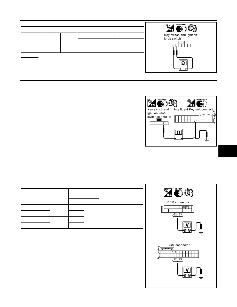
CHECK IGNITION KNOB SWITCH CIRCUIT
1.
Disconnect Intelligent Key unit connector.
2.
Check continuity between Intelligent Key unit connector M34 terminal 27 (L/W) and key switch and igni-
tion knob switch connector M22 terminal 2 (L/W).
3.
Check continuity between key switch and ignition knob switch
connector terminal 2 (L/W) and ground.
OK or NG
OK
>> Replace Intelligent Key unit.
NG
>> Repair or replace harness between Intelligent Key unit
and key switch and ignition knob switch.
Check Door Switch
INFOID:0000000001327857
CHECK DOOR SWITCH (EXCEPT BACK DOOR SWITCH)
1.
CHECK DOOR SWITCH INPUT SIGNAL
1.
Turn ignition knob LOCK position.
2.
Check voltage between BCM connector and ground.
OK or NG
OK
>> Door switch circuit is OK.
NG
>> GO TO 2.
2.
CHECK DOOR SWITCH CIRCUIT
Connector
Terminal
Condition
Continuity
M22
1
2
Press ignition knob
Yes
Return ignition knob (Re-
lease hands from ignition
knob)
No
PIIA9929E
27 (L/W) - 2 (L/W)
: Continuity should exist.
2 (L/W) - Ground
: Continuity should not exist.
PIIA6743E
Item
Connector
Terminals
(Wire color)
Door
condition
Voltage (V)
(Approx.)
(+)
(-)
Driver side
B14
62 (W)
Ground
CLOSE
↓
OPEN
Battery voltage
↓
0
Rear LH
63 (P)
Passenger side
M3
12 (P/B)
Rear RH
13 (P/L)
PIIA7003E